The Royal Hospital for Seamen at Greenwich acquired the Alston Moor Mines from the Crown in 1735 and began driving the Rampgill Horse (Low) Level the following year. The London Lead Company took over the lease on the Rampgill Vein in 1756 recommencing work on the Horse Level in 1778.
Two years earlier, work had started on driving the Nent Force Level from Alston. It was originally driven at a width of 3' 6" but this was, in 1777, enlarged to 8' square so that it could be used as a canal to carry out waste rock from the mines it intersected.
In the 19th century, the canal part of the level proved useful as a tourist attraction. By 1805 the level had been driven just over 2 miles and it was estimated that the remaining 5000 yards to Nenthead would take a further 36 years to drive. Throughout its length, the level followed the line of the River Nent.
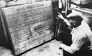
By 1815 it became uneconomical to continue the level at the original altitude of 890 feet and the eastern continuation from Nentsberry Shaft was 270 feet higher. The level to Rampgill Vein and the 328 feet deep Brewery Shaft was completed in May 1839 and was commemorated by a stone plaque above the portal in Alston. (The plaque is now stored in the town hall). An extension from Brewery Shaft to the Low Whimsey Shaft on Rampgill Vein was driven in the 20th Century by the Belgian Vielle Montagne Zinc Company who bought the leases in 1896.
The VM Company’s success was due in part to the introduction of modern machinery driven by compressed air.
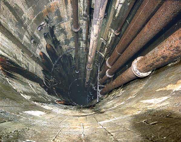
Initially the air was supplied by a steam powered compressor plant but between 1803 and 1915 the steam plant was gradually replaced by a system of hydraulic compressors using water from three local reservoirs, Smallcleugh Dam, Perry’s Dam and Coalcleugh Dam. One set of compressors was located in a chamber excavated at the base of Brewery Shaft. Water from Smallcleugh Dam was carried in a 12" iron pipe (much of which is still visible on the moor) to the top of a 90 foot tower above the shaft. At the top of the shaft, air was admitted into the feed pipe and was sucked down by the descending water. At the bottom of the shaft the air was collected in a bell shaped air receiver. The escaping water was led up a pipe to the Rampgill Horse Level 260 feet above and compressed the air in the receiver. This water was then directed back down the shaft by a third pipe to turn the 80 and 140 horsepower Pelton Wheels in the engine chambers.
These wheels drove air compressors and an electric generator. The outflowing water was discharged along the Nentforce Level. The compressed air was used for driving drilling and winching machinery, pumping and ventilation. It was carried underground in a complex network of iron pipes. Surplus electricity from the generators was fed to Nenthead Village, the first community in the area to receive an electrical supply.
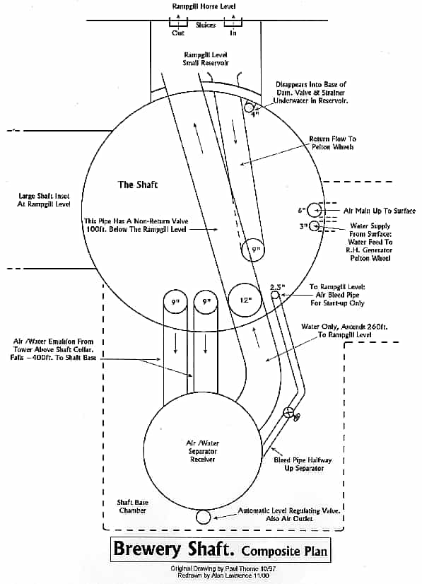
Figure 1 superimposes the shaft plan at Rampgill Level and the shaft bottom. The two sluices leading between Rampgill Low Level and the small reservoir or settling pit, allow some flexibility of water use. Extra water could be fed from the level to power the Pelton wheels if the lower sluice was opened, whilst if too much water was returning up the largest pipe from the separator, then the upper sluice allowed water to overflow into the level.
The 4" pipe leaving the base of the small reservoir was not seen at the shaft bottom and its purpose needs further examination while travelling in the shaft itself. Approximately half way down the shaft is a stone arched tunnel leading off, perhaps five feet high. This appears to descend steeply out of sight after a short distance. Its purpose is unknown but it may lead to a small shaft which comes out above the waterwheel near the connection to the Nent Force Level.
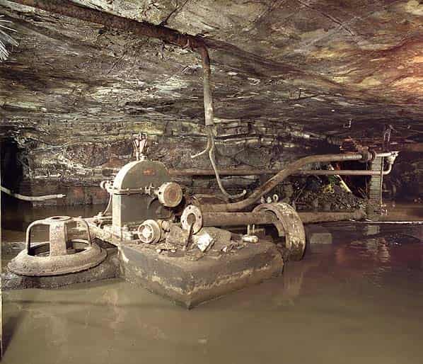
Figure 2 identifies how the sources and destinations of the compressed air are interlinked. As one would expect, there are various manually operated valves to cater for different operating conditions and maintenance. The most interesting section is that surrounding the separator/receiver. The inside of the regulating valve is my conjecture. However a simple float operated valve should work here because it would not see any significant differential pressure across the top air valve; all it is doing is basically keeping the water surface at a level about two thirds up the vessel. When operating, the ‘water surface’ would be in a highly turbulent state as the air floats upwards out of the incoming air/water emulsion. This emulsification process would have occurred at the top of the 90 foot tall tower that used to stand above the shaft collar until 1954. Here the air was entrained with the column of water falling 400 feet down the two 12" pipes. The air inlet is described as through ‘snore’ holes; presumably a very apt name. A photograph of the tower clearly shows three large pipes running up it, one would be the water feed from Smallcleugh Dam with the other two pipes descending the shaft.
The waste water re-ascends through a 14" pipe to the reservoir at Rampgill Horse Level 260 feet above. This is about the right head needed for an air output up to 90 pounds/square inch, if allowance is made for some air remaining entrained in the wastewater, thus reducing its density.
The inside of the bottom half of the separator presumably contains baffles to aid the separation. The 2.5" pipe leaving the vessel over half way up I believe would be necessary to allow the system to self bleed during start-up to avoid becoming air locked. This pipe is open at Rampgill Level (roof level) and during normal running the head of water in it would prevent escape of air or water from its open end. About half way up the 14" return pipe is a non-return valve, presumably to prevent any possibility of the water in the pipe running back into the air inlet pipe during shut-down.
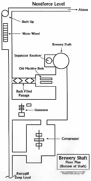
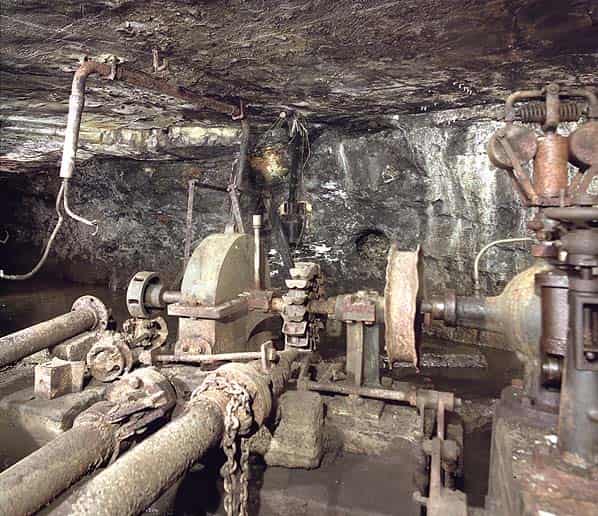
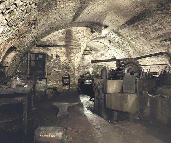
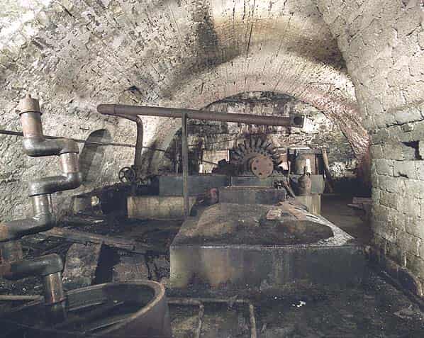
The appearance of the arching in this engine room suggests that it was constructed in two stages, the join between the two different types of arching being slightly untidy. All the machine beds within are of cast concrete.
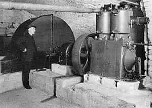
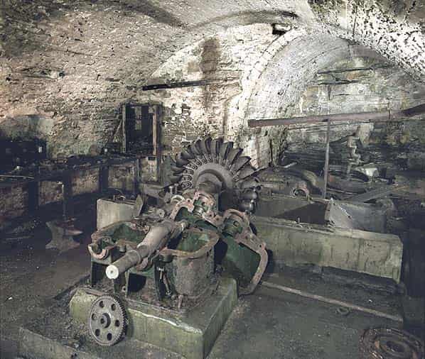
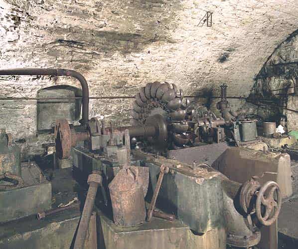
The large Pelton Wheel (Figure 3) is said to be 140 horsepower, made by Kilkes of Kendal and installed in 1905; there is no obvious nameplate visible now. Control is manual with a hand wheel controlling the spear.
Power is taken off both ends of the Pelton Wheel shaft to two reduction gearboxes, I would estimate a reduction of 3 or 4:1. All that remains is the casing of one gearbox. The gearboxes would drive one compressor each.
There are two compressor crankshafts remaining, one with a large flywheel attached; one is quite a bit larger than the other. Broom and Wade, Engineers of High Wycombe must have made one or both as a cast iron name plate remains. It is clear from a photograph of the machinery in use that the larger machine was a two cylinder tandem, single acting, single stage, water cooled compressor; i.e. a fairly basic design.
The workbenches and cupboards in this engine room contain various tools and spare parts as would be expected. The connecting rods from one of the scrapped compressors also lie here.
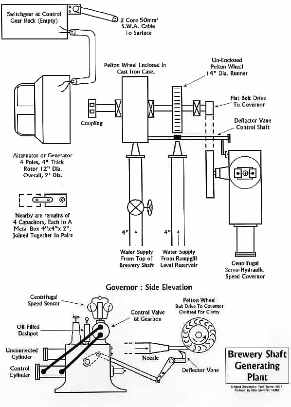
Figure 3 shows the generating plant which is driven by a twin arrangement of Pelton Wheels, each having an independent water supply. The right hand Pelton Wheel has a somewhat cobbled together appearance with its pipe and nozzle lashed to its left hand neighbour. It also has no cover fitted now or any remains of the fittings for one. A figure of 80 horsepower has been stated for the generator.
The speed governor mechanism is a sophisticated unit which uses a weight and spring loaded centrifugal unit to control a hydraulic valve (missing). The valve output feeds a control cylinder that operates the deflector vanes, thus able to deflect part of the water jet that will control the speed. There is an upper cylinder on the governor which has no obvious purpose.
The electrical output from the generator/alternator I would assume to be a single phase AC at perhaps 110 or 220 volts. One clue is the remains of four capacitors near the unit; these would not have any use on a DC system.
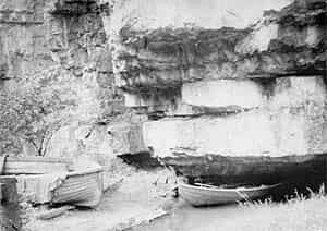
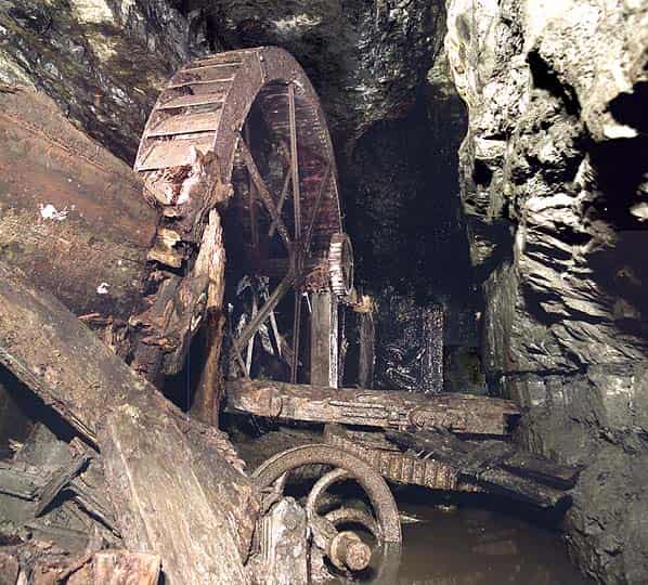
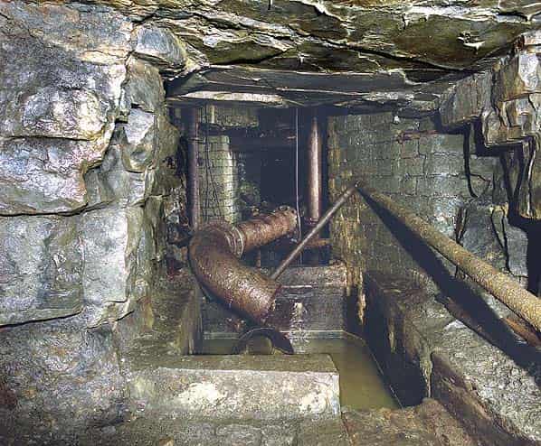
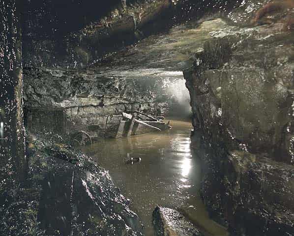
Near the connection to the Nent Force Level is a 15' iron waterwheel. Power from this appears to be geared down about 1:3 by some extremely worn iron gears. The rest of the machinery is very ruinous but a rocking beam, some chains and two cast-iron pulley wheels are visible. The water feed still runs down from the shaft nearby, maybe connected to the arched tunnel visible part way down Brewery Shaft.
The purpose for the wheel is not obvious. Nearby, part of the level floor has been turned into a concrete channel which might have been to prevent water falling into a trial below. Indeed there is a flooded hole in the floor here which is traversed using rails, but the hole is currently only about five feet deep. The rocking beam and chains may have been used to operate pumps but there is no sign of any winding gear. Another possibility is that the waterwheel feed water shaft continues under the level. This area is choked with debris making examination difficult.
In 1949 the assets of the Vieille Montagne Zinc Company were sold to the Imperial Smelting Corporation Ltd. and put under the control of one of its subsidieries Anglo-Austral Mines Ltd. but the mines were quickly run down and abandoned. Flourspar mining continued until 1960 when it became uneconomic and the final batch of flourspar was processed at Rampgill Mill in 1961. In 1970 British Steel took over the whole of Alston Moor to explore for Flourspar
For 35 years the old buildings around the Rampgill Horse Level portal remained empty until 1994 when the site was acquired by the North Pennines Heritage Trust who began a multi-million pound restoration project which led to the opening of the Nenthead Mines Heritage Centre. The site is now a scheduled ancient monument and a site of special scientific interest. Work is ongoing with a major grant from the Heritage Lottery Fund and further grants from English Partnerships and English Heritage.
To date, none of the mine entrances (excepts Carrs which is now a show mine) have been locked. Although access for the inexperienced is discouraged, the Trust is happy for competent and experienced groups to explore the abandoned mines but they ask to be informed of each visit. Rampgill Horse Level is located (NY78184351) adjacent to the entrance to the Heritage Centre and the level intersects Brewery Shaft after two hundred feet.
The Nent Force Level failed in its purpose of discovering any major new lead deposits. It did, however, facilitate the exploration of the mines it drained and served as an important spillway for water from the compressors and turbines at the base of Brewery Shaft.
The portal at Alston was blocked in the 1950’s, damming the water in the level to feed the Alston Foundry. The entrance is now open but gated. Parts of the level can be explored from the various shafts. Nentsberry Haggs Shaft is at NY7764540, Wellgill Shaft is at NY783346 and Brewery Shaft is at NY783435.
The best point of access is from the Horse Level where the shaft can be laddered or descended by SRT.
The top of the shaft is on private ground, until recently it was covered with concrete sleepers but now has a new visitors centre on the top. There are however occasional winch trips arranged by caving and mining clubs for their own members; but generally there is no public access by this route and winch trips have to be arranged with the North Penines Heritage Trust.
Technical and historical information from ‘Nenthead Mines’ by Martin Critchley (published by Peak District Mines Historical Society and ‘The Mines of Alston Moor’ by R.A.Fairbairn (published by Northern Mines Research Society). The interpretation of the underground engine chambers and machines is by Paul Thorne of the Kent Underground Research Group who also organised the winch trip. Nick Catford of the Kent Underground Research Group and Subterranea Britannica undertook the photographic survey in 1997 with the assistance of Mike Moore of the Shropshire Caving and Mining Club.