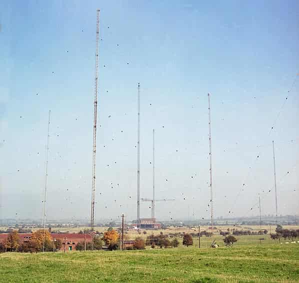
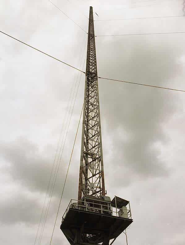
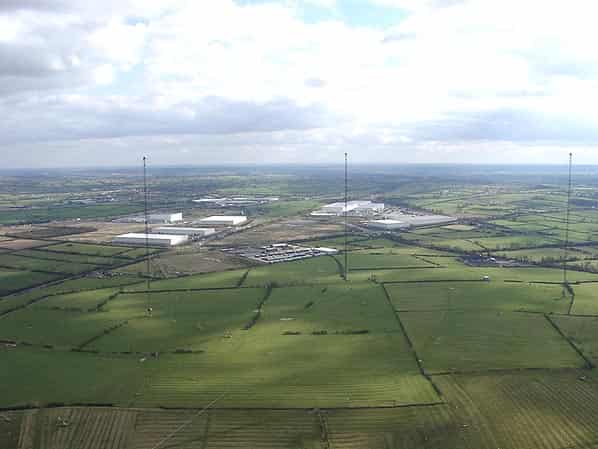
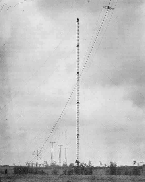
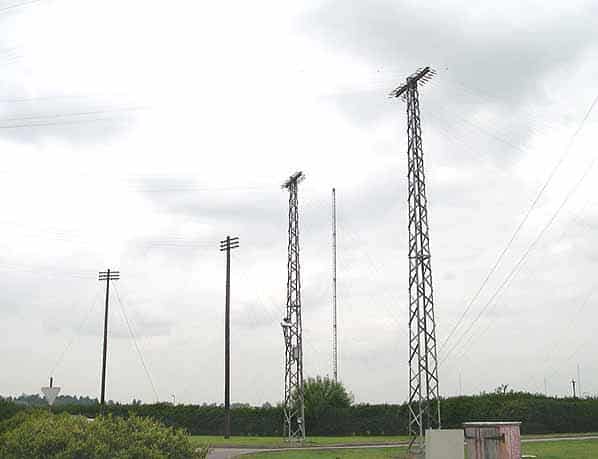
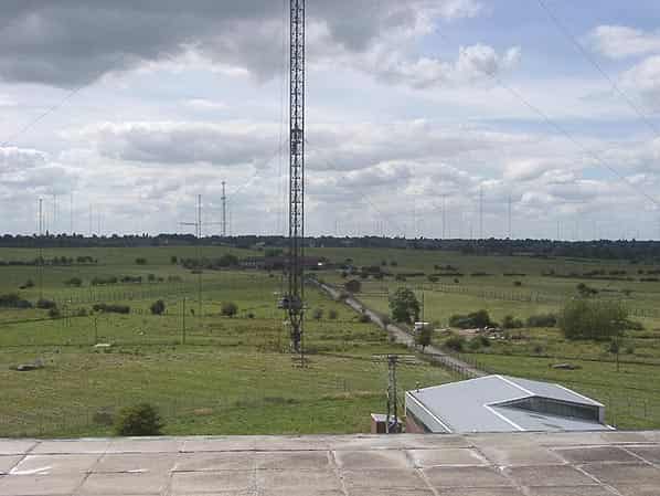
The tall masts of Rugby Radio Station (some 820ft high) are a familiar landmark to travellers on the M1 motorway, A5 trunk road and West Coast Main Line railway. In the near future all but two will be demolished, making this an apt time to investigate Rugby. The radio station described below belonged originally to the Post Office and after privatisation, to British Telecom.
Rugby radio station lies astride the A5 trunk road (the ancient Watling Street Roman road). The road marks the western border of the ancient Danelaw territory and is the county boundary, meaning that half the station is in Warwickshire and the other in Northants.. The nearest habitation is the village of Hillmorton, now a suburb of Rugby.
Rugby’s sole continuing function is to transmit time signals of guaranteed accuracy, derived from the standard time clock run by the National Physical Laboratory (NPL). As well as setting vast numbers of radio-controlled clocks in Britain the NPL’s time signal has many other interesting applications. When you call the speaking clock, or hear the time ‘pips’ on the radio, for instance, the time is derived from the NPL’s atomic clock. Rugby’s radio telephony roles were given up some years back.
Some secrecy has always surrounded Rugby’s third role, although even then a number of publications suggested that its role was chiefly defence-related, providing worldwide radio coverage on the very low frequency (VLF = long wave) band to ships and submarines (the station had nothing to do with the BBC and was never used for broadcasting to the public).
A newspaper article this year (2003) sums up what might be considered common knowledge when it states:
“Although the exact role is wreathed in secrecy, it is believed it acts as a contact point for nuclear submarines across the world and was a ‘Category A’ target during the Cold War.”
The Trident Ploughshares website is more explicit and asserts the station commanded Trident submarines, saying:
“The main sites for command and control of Trident submarines include Criggion, Rugby, Anthorn and Inskip. These sites normally consist of radio masts and little else. Command and control systems begin with the Ministry of Defence in Whitehall, London. Actual operational instructions are transmitted from RAF Northwood. However, Trident is also linked into the US command and control system and with various NATO systems.”
However, Peter Hennessey’s book The Secret State (revised edition, 2003) blows away any remaining doubt with the statement,
“Among [the Russians'] military targets were the very low frequency signals installations at Rugby and Criggion, whose purpose was and is to relay the Prime Minister’s instructions to the commanders of the deterrent-bearing submarines.”
HISTORY
In the early part of the 20th century, the British government showed considerable interest in developing a series of powerful radio transmitters that would join the British Empire together via radio links.
Some of this work was completed by the Marconi company but the government decided to build its own Post Office-run communication station to avoid being reliant on Marconi.
Hillmorton, near Rugby, along with Leafield in Oxfordshire, were chosen as excellent sites for transmitting.
Both were located in central England with large areas of flat land (Rugby was a former Royal Naval air station of First World war vintage).
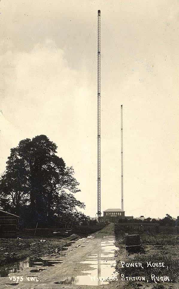
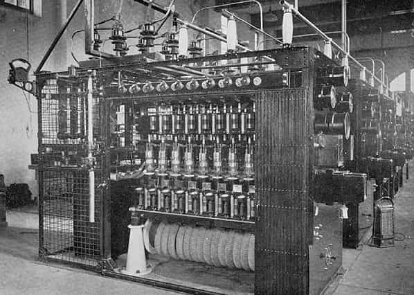
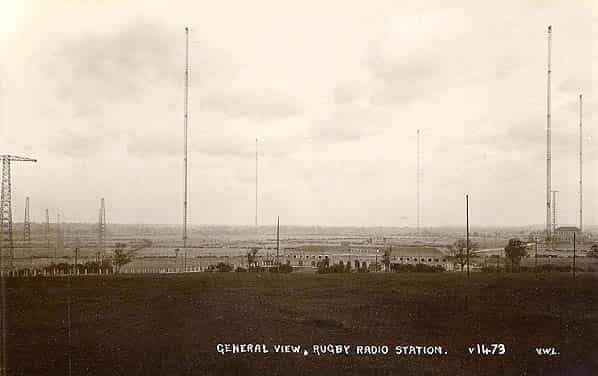
The Post Office long-wave wireless station at Hillmorton, near Rugby with worldwide range, was brought into service on 1st January 1926. At the time the station was the most powerful in the world, being equipped with a huge water-cooled transmitter (call sign GBR), dissipating 10kW and using 54 thermionic valves on a wavelength of 18,750 metres.
Initially, it commenced transmission in Morse code on 16kHz with an aerial power of 350kW. At the time it was the world’s most powerful transmitter using thermionic valves.
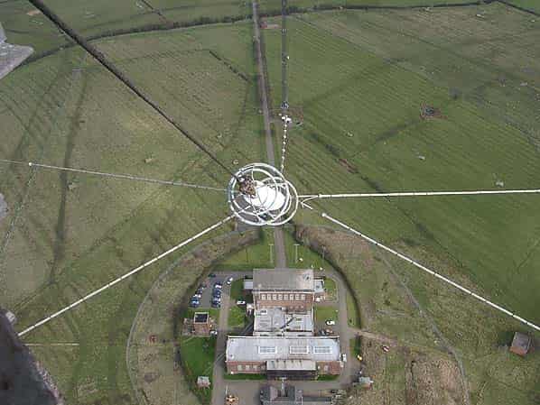
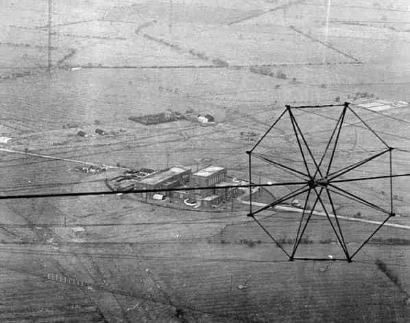
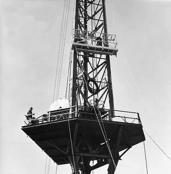
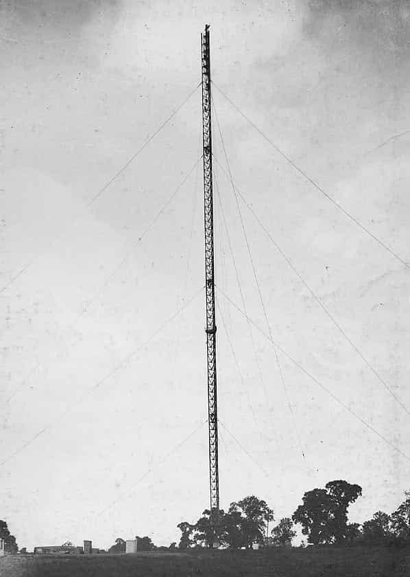
Later in the same year two-way conversation by radio telephone was also established for the first time between England and the USA from Rugby. There were twelve 820 feet masts each weighing 200 tons, with a three-man lift in the centre, supporting 27 miles of copper cable.
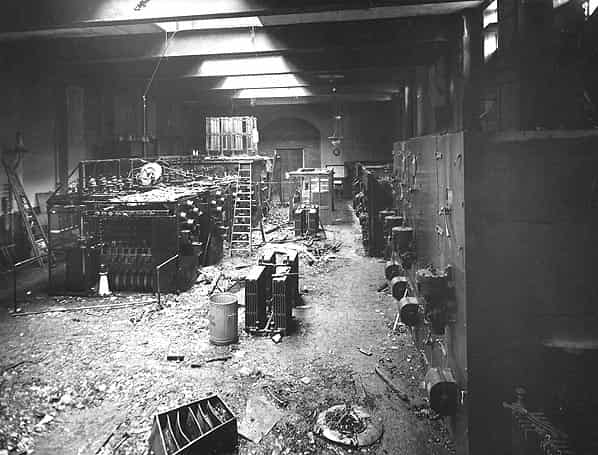
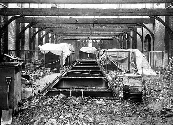
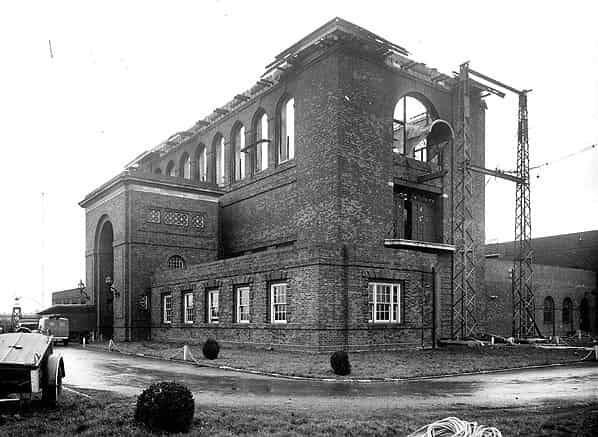
During World War II many of Rugby’s transmitters were used by the armed forces. In January 1940 the main antenna collapsed under the weight of ice and in March 1943 a disastrous fire put the VLF transmitter out of action for a while; its role was taken over by Criggion
Additional transmitters were installed in a new building in 1953 and the power supply was renewed.
SITE VISIT, 28 MAY 2003
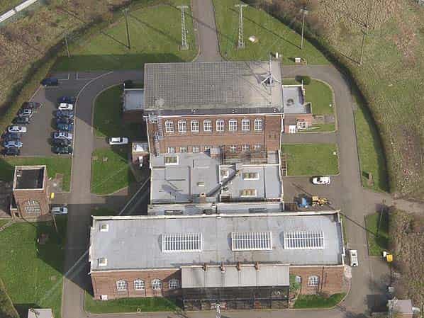
Sunny weather again favoured this visit to BT’s Rugby Radio Station in Middle England on Wednesday 28th May. It was the western half of the site that we visited; the 1953 HF transmitter house and office complex is on the other side of the road.
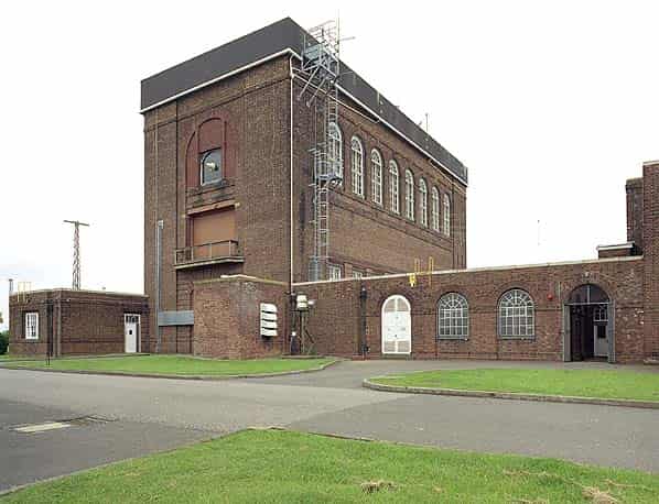
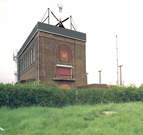
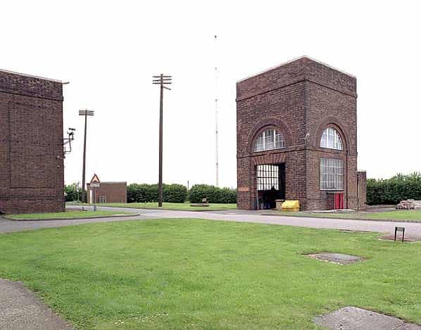
Our purpose was to see the ‘C Building’ transmitter hall of the original Rugby radio station that was erected in 1926. One of its first links was the transatlantic telephone connection to the USA, replaced after the first underwater telephone cable (TAT1) was opened in 1956. Until 31st March Rugby operated a 16kHz VLF transmitter (callsign GBR) for transmitting to submarines as at Criggion but this is now out of use.
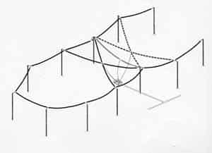
The sole remaining task of Rugby radio station is transmitting the time signal (callsign MSF) used by the radio-controlled clocks you buy at Argos, Maplin Electronics and elsewhere and this will continue until BT’s contract expires in 2007. In the near future all the antenna towers will be demolished except the two holding the ‘T’ antenna of MSF.
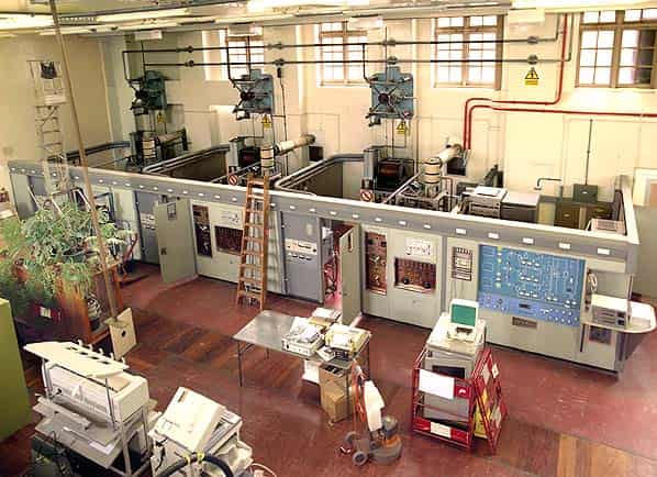
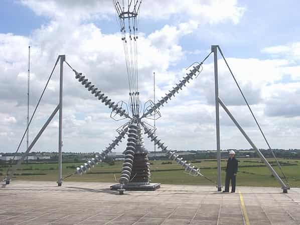
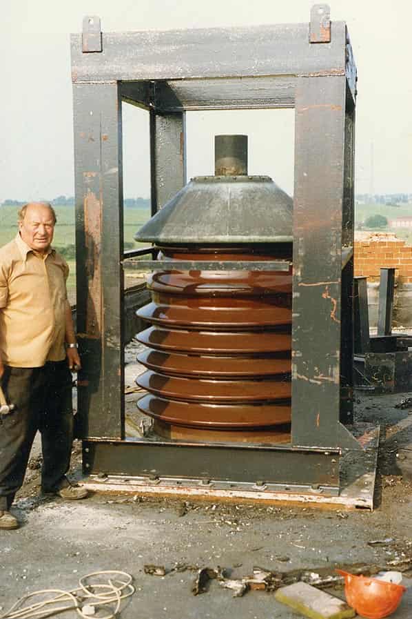
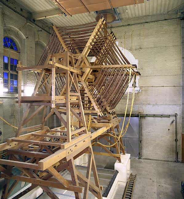
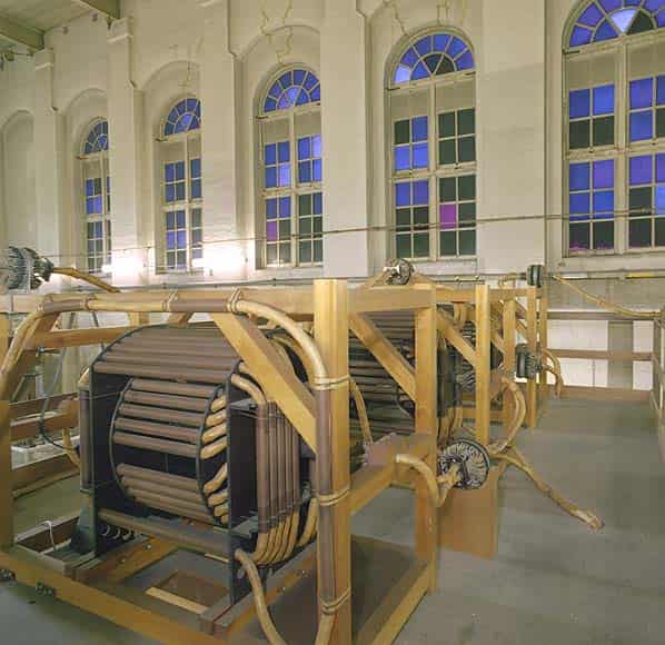
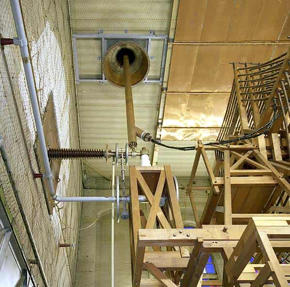
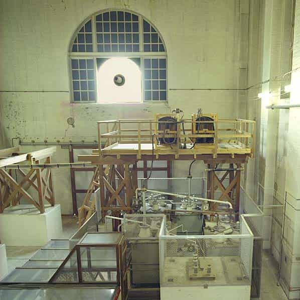
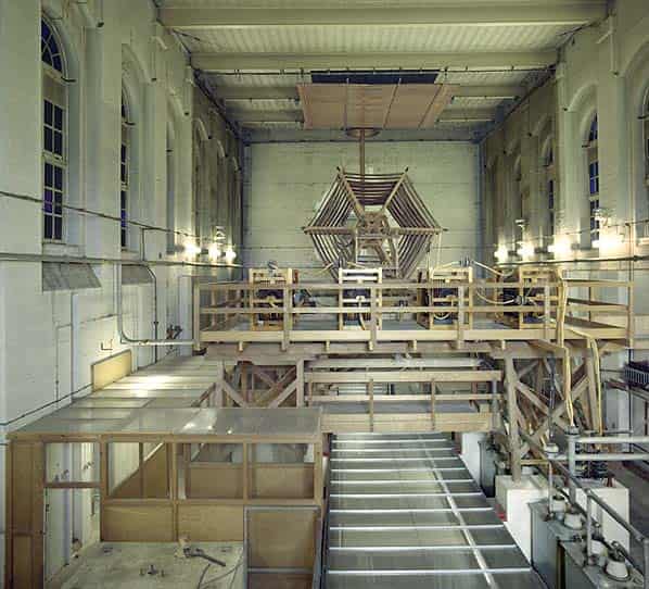
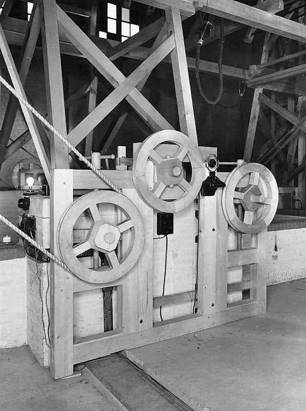
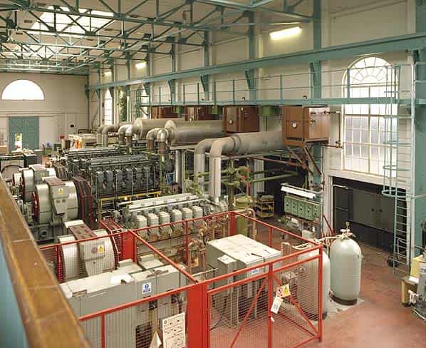
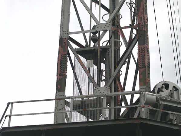
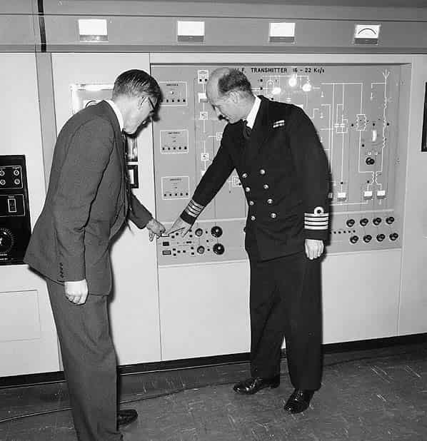
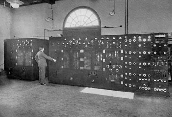
Our tour first visited the coil room on the upper floor of the transmitter hall. The vast arrays of copper ‘plumbing’ were similar to those of Criggion but in the larger building looked more impressive. All of this was supported on wooden framing held together with plastic bolts (no ironwork allowed that might detune the radio performance). The apparatus was built to carry 1000 amps of radio-frequency current, although it normally operated at 750 amps. The frequency transmitted was 16kHz normally, although tests had also been made at 22kHz. The transmitter valves operated with an anode voltage of 12 kilovolts, supplied by some pretty powerful power transformers or else by standby generators that we saw later in the power hall. Transmissions were normally MSK (Minimum Shift Keying, a form of FSK-Frequency Shift Keying-used to carry digital information on a radio carrier) and occasionally A1 (on-off keying or ‘OOK’).
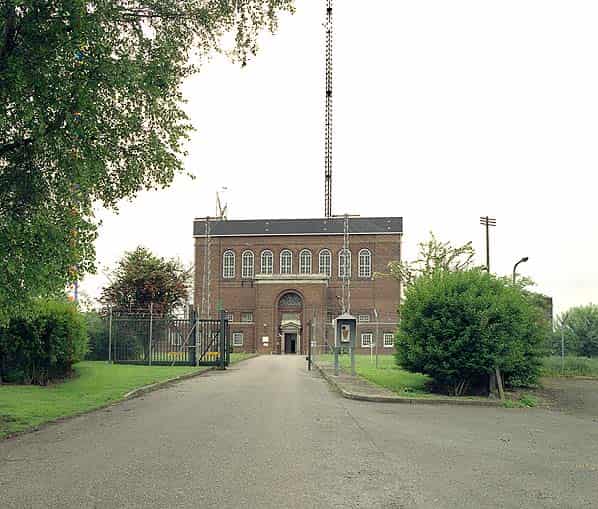
The architecture of the transmitter hall was a restrained neo-Georgian favoured by the Board of Works and we noted what appeared to be some artistic stained glass in the windows. In fact it was blue and purple plastic to filter the colour of sunlight that might otherwise trigger the fire alarms (the place suffered a disastrous fire in 1943, not due to enemy action).
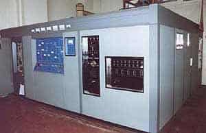
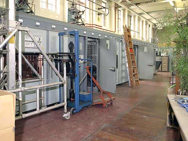
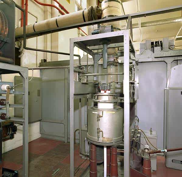
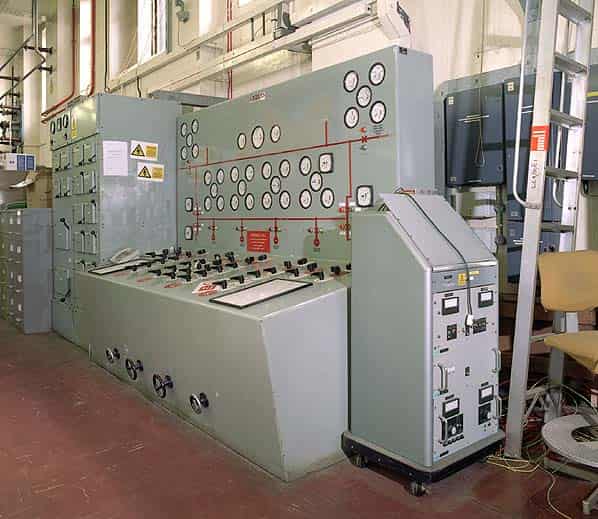
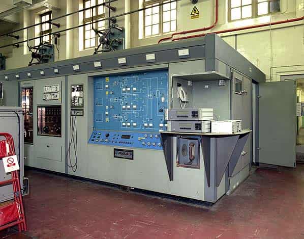
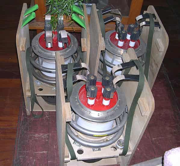
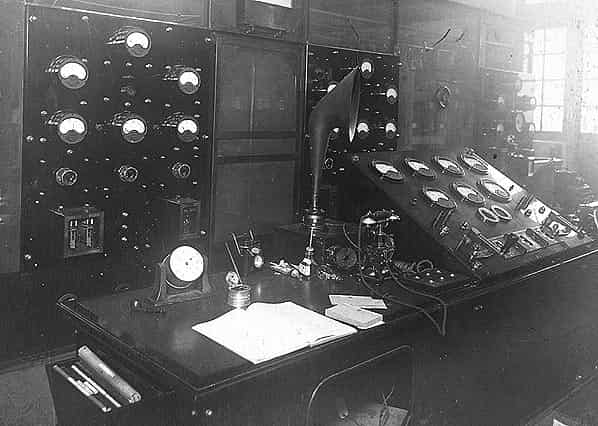
We then went downstairs to see the transmitter room. Much of this was very 1960s in appearance, with polished grey metalwork, bronze control panels and engraved Perspex signs. The spare valves are kept in a teak and glass display case, looking just like a museum! All the old valve monster transmitters are now disconnected, with just around the corner the modern solid-state Telefunken MSF transmitter and an older standby unit for MSF.
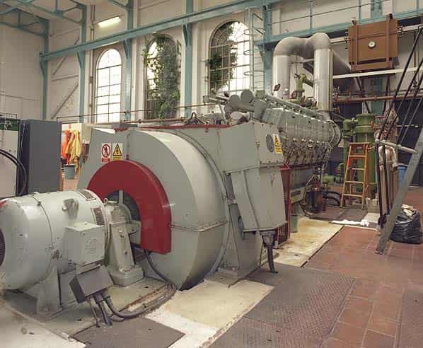
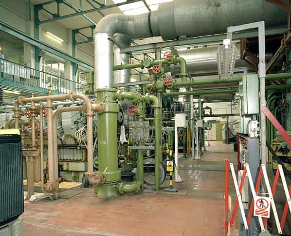
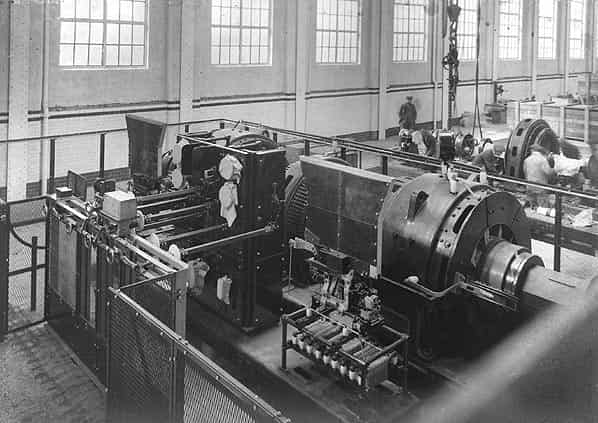
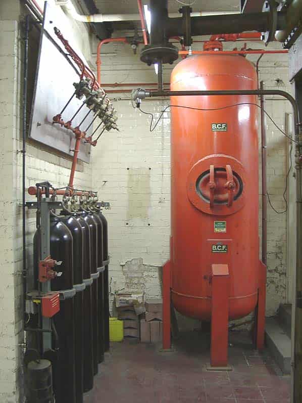
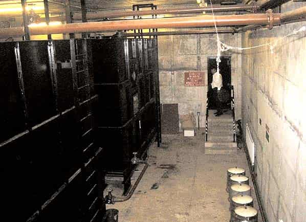
Then to the power hall and its gallery, where the staff have assembled a very worthy museum (which it is hoped will find a new home shortly).
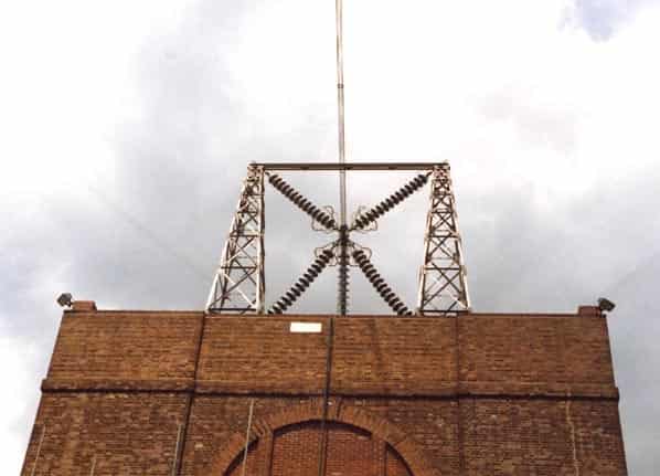
Close to and surrounding the transmitter hall are several elderly and fairly stout telegraph poles with long arms and many insulators and wires. The arrays are striking as they look incredibly neat and tidy to the trained eye. In fact these are all connected to earth and form an ‘earth mat’ to improve the radio performance of the transmitter.
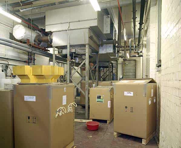
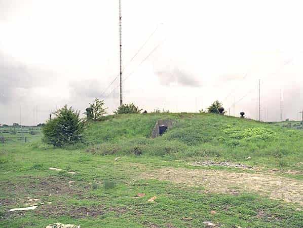
20 yards to the south of the generator hall are the buried fuel tanks for the generators. They consist of into two bunded concrete lined rooms linked by a door between; each room is big enough to house a couple of squash-courts. There are four massive oil tanks, two in each room. The tanks are semi-sunken with three metres below ground and three metres above which is covered with soil and grassed.
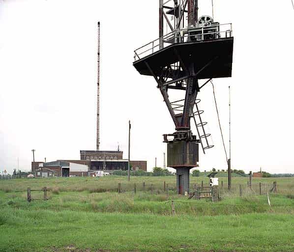
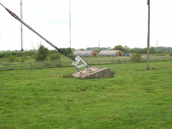
We had a walk to one of the towers and a quick photography session. In the distance was the 1930s-built HF (short wave) building, now disused, and nearby two wartime Nissen huts still used to house stores. And that was it.
This visit was a private trip arranged by a Sub Brit member, with numbers strictly limited by our host. Many thanks are due to the BT staff, who showed us round and answered our questions with great patience.
DEMOLITION
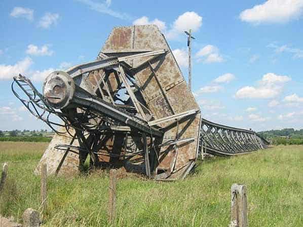
Eight of the twelve 820' masts at Rugby were due to be demolished by DSM Demolition contractors during the evening of of 19th June 2004. The Police had insisted that the demolition should take place in the dark and without prior publicity in order to avoid having to close the M1. As it was, they still had to close the A5 and A428 immediately prior to the demolition taking place.
The method of demolition was to simply cut one set of the four support guy ropes for each mast. The tension on the other three support ropes then pulled the mast in the desired direction. Demolition charges were applied to each of the three stay ropes at their base, the metal bracket joining the ropes to the concrete stay block having been pre-weakened. The ‘shaped’ cutting charges were linked together to fire simultaneously for each individual mast.
The eight masts were due to be demolished in two phases. The first phase of the three most northerly masts went down at about 21.45 with two seconds between each mast. It was a text-book demolition with all three masts falling ‘clean’ and in exactly the right place.
The second phase of the five southerly masts was due to take place two minutes after the first phase, this being the time taken for the demolition engineer to move from one firing point to the other. The count-down began and we all expected a similar result to the first phase. Alas, it was not to be. Nothing happened. Half an hour later they had reconnected the command lines and tried again. The fourth mast went down but none of the others.
Half an hour later they tried again. The fifth mast went down but not the final three! An inspection of the command lines revealed that each had been ‘nibbled’ by rabbits! It seems that bunnies are partial to detonation cord. Despite the cord having been laid down a maximum of eight hours before, all the southern command lines had been severed!
At about 01.00 on Sunday morning, new detonation cord having been applied to each charge, they finally pressed the button and the final three masts fell, slowly and imperceptibly at first, then with increasing speed, hitting the ground in a shower of sparks as the rivets sheared away. The sound of the demolition was distinctive with the bang of the cutting charges followed by a distinct “crinkling” noise from failing rivets and a final thunderous roar as the 250m masts folded into the ground. Despite the unexpected delay, the masts fell in the right places and as a demolition exercise it has been a great success.
With only four masts remaining the Rugby skyline all looks very different.
OFFICIAL HISTORY
The history of Rugby Radio Station, by Malcolm Hancock (former Station Manager)
Sources:
- Andrew Emmerson
- Bob Jenner
- Steve Pell
- Nick Catford
- Rugby Radio Museum
- Creighton, J.L. The New Very-Low-Frequency Transmitter at Rugby Radio Station. Post Office Electrical Engineers' Journal January 1969 (Vol. 61), p.232
- Gracie, J.A. Rugby Radio Station. Post Office Electrical Engineers' Journal April 1939 (Vol. 32) p.16
- Faulkner, Brian. Rugby Radio Station. Radio Bygones, April May 2002, pp 14-20
- ‘Something in the air - a guide to the Ruby Radio Masts’ by Pete Chambers