RAF Ventnor was one of the 20 original Chain Home radar stations authorised in 1937 and the station first became operational in temporary hutting in late 1938. While many Chain Home radar stations around the country closed at the end of the war, RAF Ventnor remained in use and in November 1947 it was one of only 26 operational radar stations in the UK. The Type 24 long range microwave height finder and Types 52 and 53 radars were still in use while the Type 1 Chain Home radar remained on care and maintenance.
The entire station eventually went into care and maintenance. By 1950, the threat of the Atomic bomb had caused a serious rethink in the organisation of air defence and a plan, codenamed ROTOR, was instituted to replace many of the existing stations with new protected underground operations rooms. RAF Ventnor was chosen to participate as part of the first stage of the ROTOR Programme which was itself divided into four phases. Phase 1 was the re-establishment of 28 WW2 Chain Home radar stations. 13 were brought up to a fully operational state while the remaining 15 were brought up to a ‘readiness’ state. These stations would have required some notice before they were fully operational.
Phase 2 was the construction and installation of 14 new underground Centimetric Early Warning (CEW) and Chain Home Extra Low (CHEL) stations. Phase 3 was the construction and installation of 11 new underground Ground Control Intercept (GCI) stations Phase 4 was the construction of 14 new semi-submerged or above ground GCI stations.
A CEW station was designed to provide the first contact with any attacking force. Its big advantage over Chain Home was its ability to fairly accurately assess height, range and size of an attacking force. The Centimetric Early Warning system needed to be situated at least a 100 feet above sea level and sited relatively close to the coast. The high position of the stations enabled the radars to have an uninterrupted sweep of the coastal approaches of which they protected. Ventnor was therefore an ideal location.
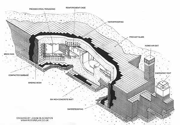
Ventnor (code OJC) was to be one of seven underground CEW radar stations (the others being Portland, Beachy Head, St. Margaret’s, Trimingham, Inverbervie & Cold Hesledon). Each of these stations was provided with a heavily protected underground operations room designated R1. Although protected, underground technical buildings were never intended to survive a direct hit from a nuclear weapon but were designed to withstand a near miss from Russian pattern bombing with 2,200lb armour piercing high explosive bombs (BRAB) dropped from 35,000 feet.
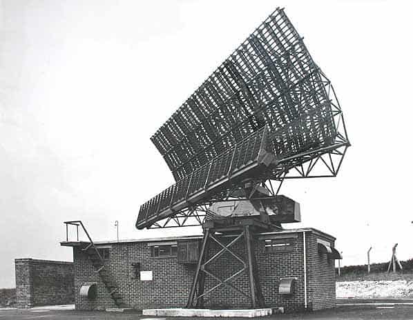
As planned, the station was to be fitted with the following radars, three Type 13 Mk, VI height finders, one Type 14 Mk.VIII and one Type 14 Mk. IX and one American AN/FPS3 and one ANTPS 10. Once development of the centimetric Type 80 radar was complted it was then planned to install this at Ventnor. At this time it was intended that both Type 14’s would be removed but one was retained as a back up to the Type 80. The projected completion date for RAF Ventnor was 1.11.1952. The Type 80 was finally handed over to the RAF on 20.3.1956.
The domestic camp and married quarters were located below St. Boniface Down and in order to provide communication between the controllers in the R1 bunker and intercepting aircraft; two VHF/UHF multi-channel radio transmitter and receiver blocks were built across the valley. The receiver was on Stenbury Down and the transmitter, quarter of a mile north on Appuldurcombe Down. These were remotely sited to avoid interference from the radars.
RAF Ventnor was manned by No. 23 Signals Unit and came under the control of the GCI station, RAF Sopley which, in turn, was administered by the Sector Operations Centre at Box. RAF Ventnor remained operational until at least 1957 but eventually closed and was placed into care and maintenance. The ‘1958 Plan’ states that the station may be required for a different purpose.
The RAF finally left the site in 1961 and the station was taken over by the Ministry of Aviation for use as a radar and communications station for the Civil Aviation Authority.
It was also used as a test location for more exotic systems, and unusual antennae occasionally came and went. A satellite dish, approximately 4 to 5m diameter, was temporarily installed nearby in the mid 1970’s. Missile tracking, the explanation advanced locally, was dismissed by former workers at the nearby Needles civilian rocket launch site, several of whose firings had resulted in unplanned splashdowns and for whom tracking was something of a painful subject.
The CAA did not require the R1 bunker and in 1962 this was gutted and refurbished as the Isle of Wight County Control Centre from where the Island would have been administered in the event of a nuclear attack. This remained operational until the end of the cold war as the Isle of Wight Emergency Centre, finally closing in 1991.
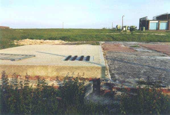
The bunker was handed back to the CAA who decided they had no further use for it. The bungalow/guardhouse, air vents and the emergency stair tower were all demolished and the shafts capped with concrete with a hatch for emergency access. After several attempts to break into the bunker the concrete cap was covered over in 2004 and the site of the guardhouse was landscaped leaving no evidence of the entrance to the R1 which still remains below ground in pristine condition.
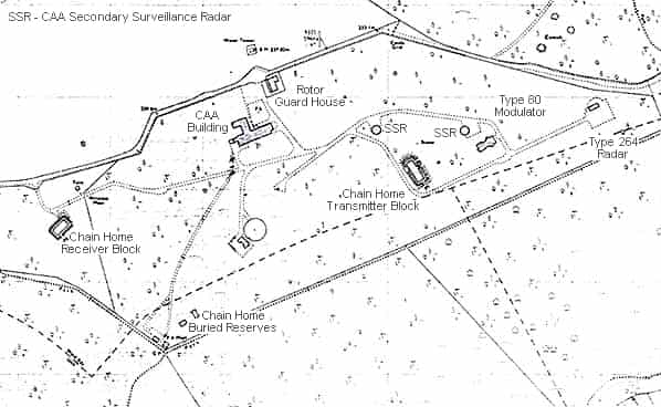
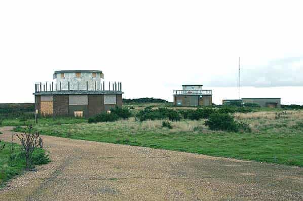
The chain home towers survived until 1957, the CH transmitter block which was within the rotor compound survived until at least 1998 but when the site was surveyed in 2004 it had been demolished. The Type 80 modulator building and adjacent redundant CAA Secondary Surveillance Radar (late pattern IFF) circular buildings still survived in 2004; these worked in conjunction with two CAA Type 264 radars which have been removed together with their gantries and buildings. The two SSR’s are due for demolition in the near future as they have proved a target for vandals and as a result the entrance doorways have all been bricked up.
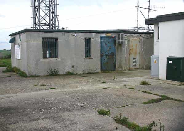
The chain home receiver building stands just outside the ROTOR compound; this is currently owned by BT but was offered for sale in late 2004 so its future is uncertain.
PERSONAL ACCOUNT OF LIFE AT RAF VENTNOR
The following is an edited description of RAF Ventnor by Don Adams who served on the station from 1955 - 1957. For a more detailed report on Don’s time at RAF Ventnor see his excellent Ventnor Radar web site.
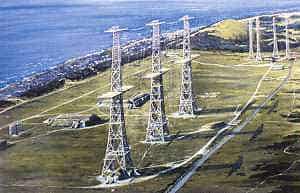
“A large enclosed area at the top of St.Boniface, 750 feet above the sea, contained low buildings and the tall old CH towers. I could see three Type 13’s nodding away benignly and a Type 14 on top of a low tower, but the whole scene was dominated by the Type 80 steadily rotating at 4 revolutions per minute. I accompanied the Warrant Officer into ‘the bungalow’ and into his office where he issued me with a fitter’s tool box, the contents of which had to be checked and signed for. .
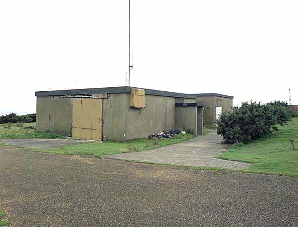
The small gray bungalow built just inside the chain-link perimeter fence somewhat optimistically disguised the entrance to the bunker. Besides providing access to the top of a circular stairway guarded by a Service Policeman, the bungalow accommodated the Technical Officer together with his Warrant Officer. The roof space was used to store a small quantity of spare units for the radar ‘heads’
The tunnel, which was about eight feet square, descended at a significant angle and was brightly lit, had smartly painted rendered walls and had a highly polished brown linoleum floor. After about 30 yards there was a wall mounted glass fronted cabinet which contained two service revolvers. It was hard to imagine the purpose of these, especially when I later learnt that the bullets for these were kept in a safe in the office above. The corridor continued, then turned sharply left and after another thirty or so yards reached a pair of massive blast doors. These were well over a foot thick and presumably motor driven, but thankfully I never saw them closed. The corridor was now at the right-hand side of a large room known as the Radar Office.
After this, doors on the right gave access to Officers' and Other Ranks' refreshment rooms and on the left, curtained access to the Operations Room. Next, also on the left, double doors led to a few steps down into a large high ceilinged ‘plant’ room housing ranks of motor generating equipment and air-conditioning apparatus. The corridor, now being only six feet across, continued through double doors and around a corner to a bolted heavy steel door through which was the main ventilation shaft which doubled as a route to the emergency exit. The shaft contained a zigzag of several flights of steel stairs and a large waterfall air washing system. Finally a heavy door in the side of the shaft, now a steel tube, opened to fresh air.
The name ‘Radar Office’ was somewhat a misnomer, the only desk being a small one for the shift diary, although there was a partitioned office in one corner. The whole room was filled with rows of rack-mounted electronics. The valve technology of that time was bulky and generated vast quantities of waste heat, so each rack was fitted with forced air cooling, and thus the noise level within the room was irritatingly high. Some of this equipment was my concern, but most was not. Each of the radar transmitters required a clock pulse to initiate each modulator pulse and these had to be in synchronism otherwise one radar in receive mode might be force fed with the pulse being transmitted from its closely adjacent neighbour, with dire result. So all clocks were derived from one master and that was generated from a crystal oscillator at a high frequency and repeatedly divided down to the 270 rate required and this equipment was deemed to be the province of the above-ground engineering staff, and was contained in but one rack amongst the serried ranks of the many others in the Radar Office.
I later learnt of the contents of some of these cabinets. For example Range Rings and Video Map, which rightly belonged to the ‘Consoles’, trained fitters and mechanics, hence I know little of the details of these, but a few words are appropriate. Range rings were concentric bright rings which, at the flick of a switch, could be made to appear on the displays at the same time as the targets. They were at set distances apart, say 50 miles, and thus the operator had an easy way of assessing the range of a target. The pulses to create the rings were generated entirely electronically.
Video Map required a little more ingenuity. Here, also switched on as desired, an outline map of the entire coastline in range, together with a grid map, was superimposed on the surface of the screen whilst still allowing the targets to be seen. The source of the map image was an acetate sheet on which all the details were drawn. Over this was mounted a lens which concentrated the image onto the aperture of a photo-electric cell. Under the acetate sheet was the face of a six inch white phosphor cathode ray tube (CRT). This did not display the radar echoes but just a bright radial line which rotated in synchronism with all the proper displays. Thus the map was scanned and the PE cell produced an output which could be distributed to the consoles as a video input.
The beauty of this system was that the timebase (operator selectable) at different consoles could be set to different ranges but the map always expanded or contracted in proportion, as did the range rings. The Video Map required careful setting up but was extremely effective, and there were two of these units in the Radar Office.
Another remarkable apparatus was the Monitoring system. This aid to fault-finding was a large-screen oscilloscope which was built into the racks at a central point and the screen could be slewed to facilitate easy viewing. It was fitted with two large rotary multiposition (perhaps 20) switches. Combined use of these allowed hundreds of crucial waveforms from countless sources within the Radar Office to be displayed. Reference to a bulky volume revealed whether or not each was correctly formed.
A curtained archway in the side of the Radar Office gave access to the Operations Room. Darkness ruled here, the only normal illumination coming from the amber and green glows of the CRT displays and that from the circular dynamic Plotting Table. At about ten feet in diameter this was in fact not a mere table, but a display of an image from a projection system which the officer in charge viewed from a tall ‘umpire’s’ chair. The targets were thus magnified to about an inch across and they seemed to swim about on a somewhat watery surface, but the broad gently illuminated area was more restful to the eye than a CRT and allowed the overall situation to be viewed for extended periods.
Arranged around the room there were sets of the normal consoles, each pair consisting of an amber fifteen inch Plan Position Indicator (PPI) driven from the Type 80 or Type 34 search radars together with a nodding height finding display from a Type 13. The origin of the trace of a PPI display was normally the centre of the CRT, but operator controls could move this to any point of the surface. If moved say to the southwest periphery then only the northeast 90 degree sector was viewable thus concentrating the operator’s interest in that area but allowing a much greater range to be monitored. The Type 34 was in fact a Type 14, but received this new title when mounted on a 25 foot high wooden gantry. This arrangement gave very good low level cover to and beyond a more distant horizon. Thus at Ventnor, shipping was effectively monitored together with low flying aircraft, the two being differentiated by the size of echo and speed of progress. Casual chatter was banned in this room; the only voices heard were those of the operators' quietly relaying information via telephone headset to a distant central Control establishment or directly to an aircraft by means of VHF radio.
Stairs in one corner of the room led down to a cellar containing the Kelvin Hughes Photographic Display Units and an associated Darkroom. The PDU provided the image for the Plotting Table. A small very bright radar display with a whitish phosphor was photographed onto Ilford HP3 35mm film once per revolution of the trace. The exposed frame moved on into a chamber where it was sprayed with developer. After a brief interval it was sprayed with water and then with fixer. A final water spraying took place and then it was blown with hot air. Each stage took fifteen seconds and a minute after the initial exposure the frame was in the projection station. The image was directed by mirrors to the undersurface of the Plotting Table in the room above.
There were two PDUs, left-hand and right-hand, both projecting towards the final mirror mounted between them. By manually flipping this over, the image from either PDU could be directed upwards. The film in the PDU was a 50 foot reel loaded in a cassette by the fitter or mechanic in the darkroom. When the film was close to the end, a buzzer in the Radar Office called for attention, as did low levels of developer or fixer. The drill was to then switch on the resting PDU and after a minute flip over the double-sided final mirror to allow the newly activated machine to provide the image. The first machine could then be serviced without haste. An additional facility provided by the PDU system was that the used film could be archived and used for post-mortem purposes after any event such as mid-air near collisions. The disadvantage of the system was that the overall picture on the plotting table was a minute late, but the viewing officer always moved to a normal console at a time of particular interest or impending crisis.
In the Cold-War context, contrary to what might be expected, there was no living accommodation down this ‘Hole’. Small rooms were provided for relaxation purposes and I believe that there was a small kitchen. I am curious about the water supply: St.Boniface is the highest point on the Island so special pumping would have been required to provide a mains supply. Undoubtedly there must have been an adjacent reservoir somewhere, but there was no above-ground water tower. Drainage would also have been a problem. The underground lavatories were akin to those used by submariners. Equipment to deal with these vital services must have existed in the Plant Room, but this would have been dealt with by civilian contractors, known within the Service as ‘Works & Bricks’.
However, I found it all very claustrophobic and was heartily glad that I was to be employed above ground and so was relieved when he led the way back up to fresh air and across the two hundred yards of gorse to the unsleeping monster that was generally known as ‘The Eighty’.
While I absorbed the unanticipated noises of the machinery, a muffled roar from the alternator room, a whine from the turning-motors and above all a hiss from the seventy foot reflector.
After a brief inspection of the modulator, the purpose of which was to produce very short pulses of very high voltage, I was shown the Signal Office Diary, the Meters Records book and the Standing Orders. Then we went out, clambered up the iron stairs to the gantry and on to the running board of the rotating transmitter cabin. A grey cabinet contained the true heart of all this equipment, the water-cooled magnetron which, fed on the diet provided by the modulator below, produced enormous 2 megawatt microwave pulses for 2 microseconds, 270 times a second for every second of every hour. These colossal bursts of energy were directed by means of highly scientific piping known as ‘waveguide’ to the focus of the giant reflector and thence bounced into the atmosphere. When the pulse ceased, the waveguide from the aerial became joined electronically to the receiver kit and any re-radiated energy from a distant target returning to the reflector would be passed on to the underground consoles.
We could see reliably targets 250 miles away and sometimes much more. This was state-of-the-art Early Warning, incredibly better than anything used in the war years. However the Type13 height finders could not match this range as they did date from the war.”
DOMESTIC CAMP
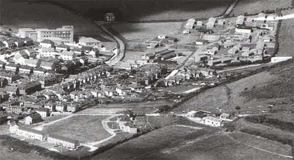
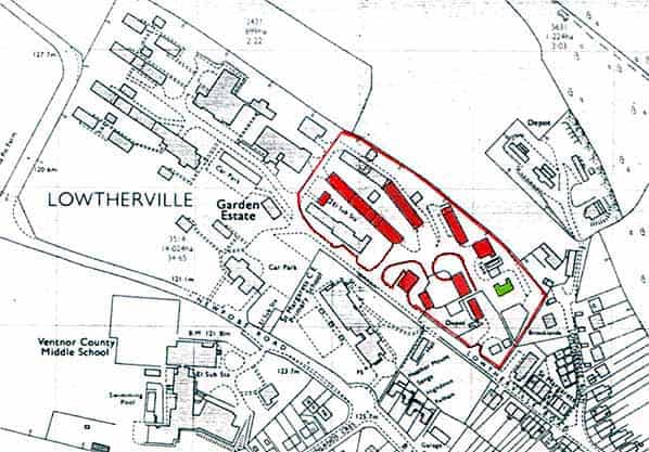
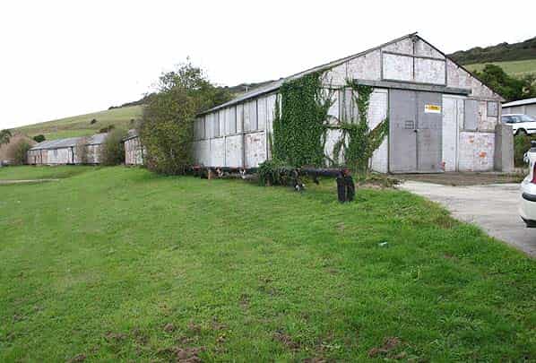
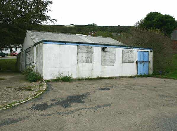
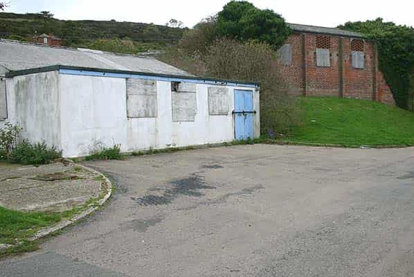
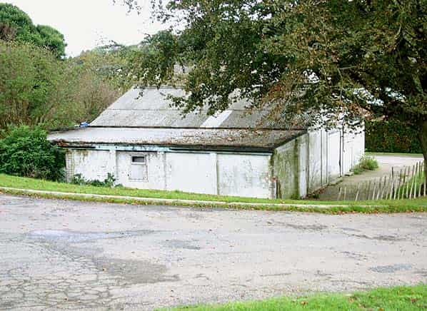
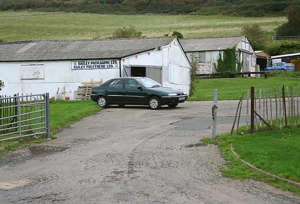
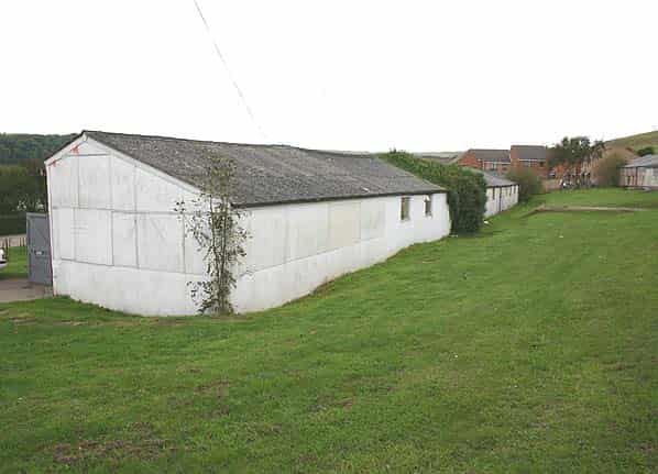
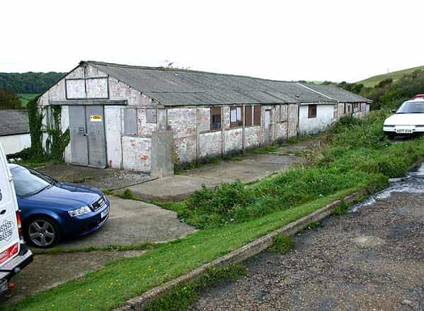
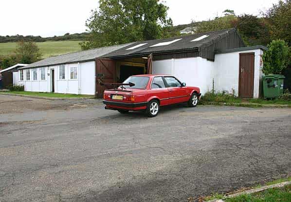
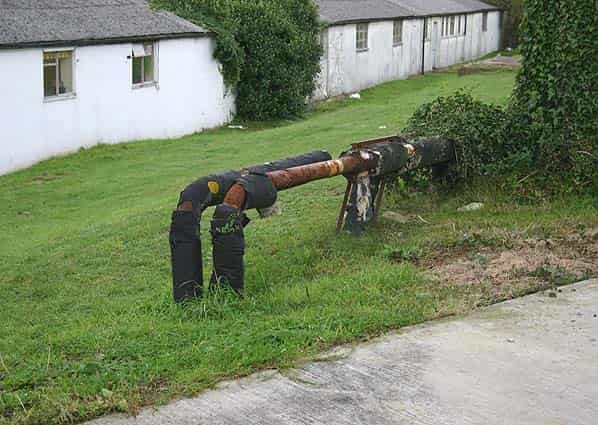
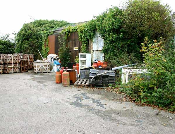
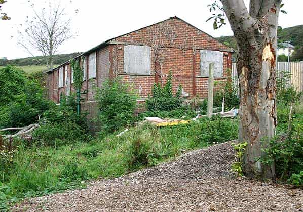
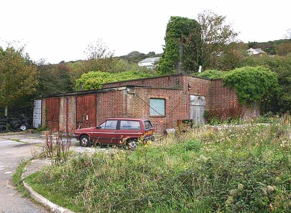
The domestic camp for RAF Ventnor was at Lowtherville, (SZ554781) a mile to the west of the technical site on the northern outskirts of Ventnor. Approximately a third of the hutted camp is still standing on the north side of Lowtherville Road. The buildings have been put to light industrial use. Remaining buildings include the guardhouse, MT sheds, boiler house, sub station and a number of accommodation huts some of which have been joined together to form longer buildings. There are plans to demolish most of the remaining buildings and redevelop the site.
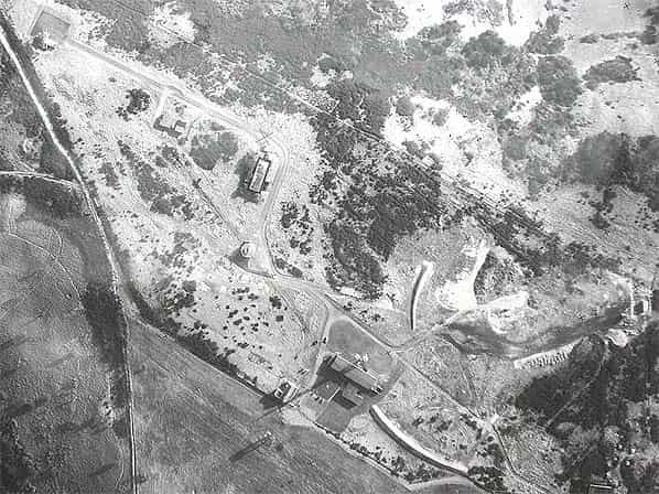
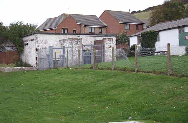
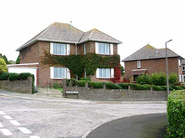
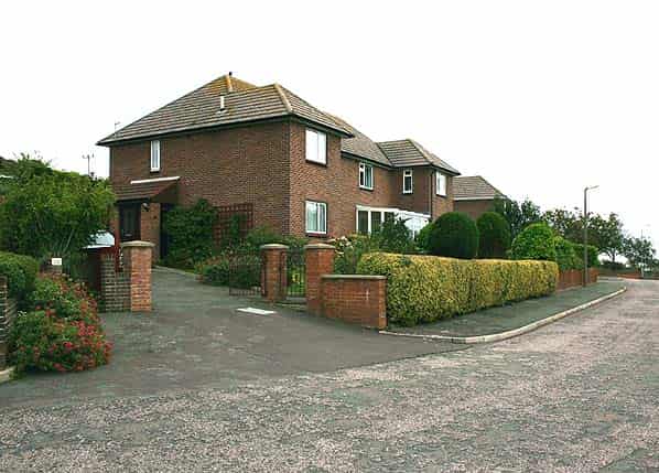
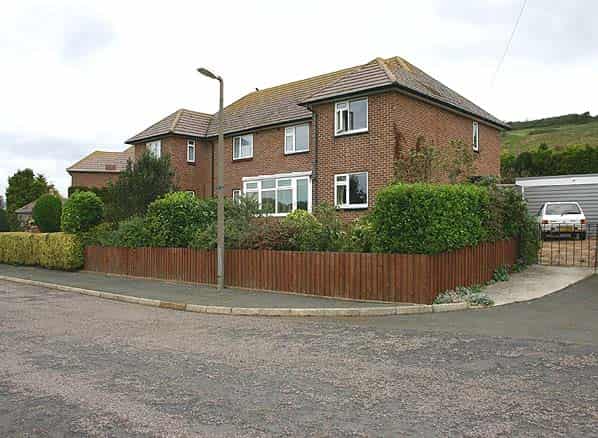
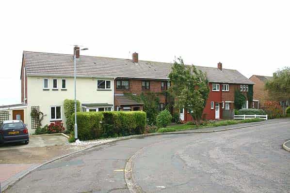
The married quarters consists of one detached house for the commanding officer, two semi-detached houses for the officers' and two rows of eight terraced houses for the other ranks. All the houses are now in private occupation. As can be seen in the aerial picture above, there was originally open ground between the officers' houses and those of the other ranks. This land has now been built on.
VHF/UHF TRANSMITTER & RECEIVER SITES
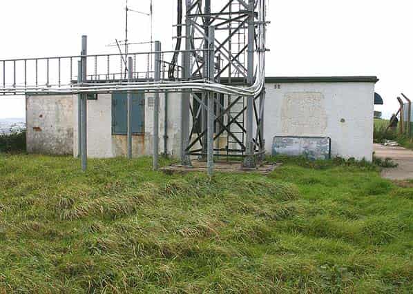
In order to provide communication between the controllers in the R1 bunker at RAF Ventnor and the intercepting aircraft, two VHF/UHF multi-channel radio transmitter and receiver blocks were built at remote sites. Transmitter and receiver blocks come in two sizes, designated ‘small’ and ‘large’; those at Ventnor, which are both still extant are ‘small’. Each block would have had a 90' wooden aerial tower alongside. The receiver tower has been demolished but the transmitter tower is still standing and is now used to support modern communications aerials. It is one of only two wooden ROTOR aerial towers still believed to be standing. Crosslaw CHEL Rotor station still has its wooden tower although this was due to be demolished some years ago.
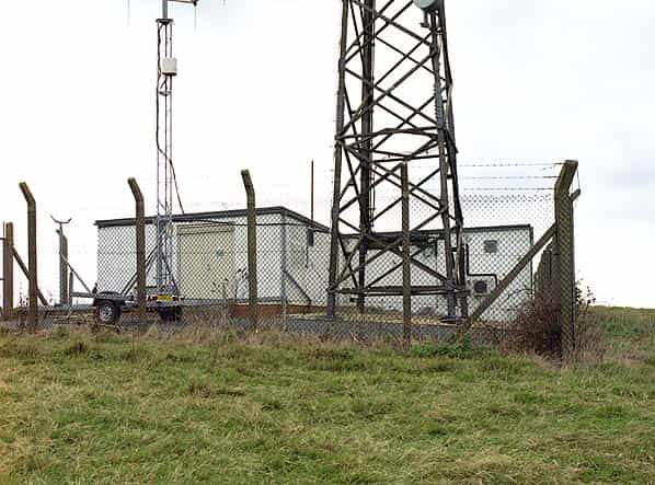
Each site consisted of two buildings, the operations building and a standby set house. The smaller receiver building which stands on Stenbury Down at SZ53897930 at the end of a dead end minor road originally comprised a receiver room, mechanical and electrical room, store, workshop, staff room and toilet . Externally there have been few alterations to the building which now houses cellphone equipment. A new cellphone mast stands in place of the wooden tower. The standby set house alongside is also still extant. An unmade track leads west towards the transmitter site 400 yards away on on Appuldurcombe Down at SZ53637968
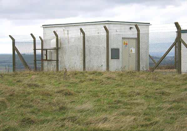
As built, the transmitter building comprised the transmitter hall, mechanical and electrical room, store, workshop, staff room and toilet. The building now houses communications equipment. The adjacent standby set house and wooden tower all within a new secure compound.
Sources:
- Bob Jenner
- Keith Ward
- Don Adams
- PRO files Air8/1630 Air8/2032 Appendix C