Originally all the radars at RAF Buchan were to be clustered round the R3 control centre apart from the Type 7 which was remotely sited 2km south west of the site on the south side of the A90.
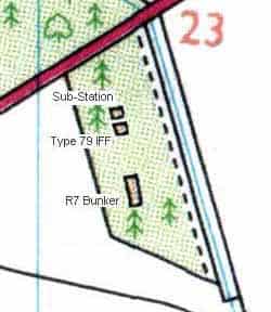
The transmitter, receiver and motor for turning the aerial array were located underground in a bunker designated as an R7 and known as a ‘well’. During the ROTOR period two different types of R7 bunker were utilised. Where the Type 7 radar was located close to the R3 operations block it was housed in an R7 Mk II bunker which consisted of a single room. If the R7 was at a dispersed location a larger R7 Mk III was built which consisted of three rooms. Because of the distance from the main site, an R7 Mk III required its own IFF and an Mk 10 IFF was mounted on a Type 14 plinth, turntable and cabin, and this combination was known as a Type 79. This was located a short distance to the north of the R7 bunker with a small brick built electricity sub station alongside.
The Type 7 was developed in the early years of WW2 as parallel development of the Chain Home Low (CHL) radar by the addition of a height-finding capability and a Plan Position Indicator (PPI) display.
Early stations were designated ‘transportable’ with a fixed version of the final Type 7 equipment being developed in 1942. The final stations comprised an Operations Building (Happidrome), a radar well and an aerial mounted over the well; the well housed the transmitter and the receiver.
Continuous tracking of targets was essential to interception procedure and the aerial system had to provide gap-free cover. To do this an array consisting of 32 centre-fed full wave dipoles was used, mounted in four stacks, each with eight dipoles. For transmission, the top four dipoles and the bottom four dipoles in each stack could be combined either in phase or in antiphase under the operator’s control. This achieved overlapping beam positions and provided adequate gap filling.
For reception the dipoles in each stack could be combined in four different ways providing beams at difference angles of elevation for height finding. Switching between beams was done automatically or on a pulse-to-pulse basis using a capacity switch in the feeders.
The antenna beam width was 15 degrees although a narrower beam width and greater range performance was provided for the ROTOR improvement plan by the addition of more stacks of dipoles on each end of the aerial.
WW2 R7’s were known as Mk. I, post war, the equipment was upgraded within the same underground structure; this was designated Mk. II and referred to as ‘Small R7’. A much larger R7 Mk. III was built at remote sites up to 2 km from the main site containing IFF facilities. Both Mks. II and III were later re-engineered to Mks. IV and V standard respectively.
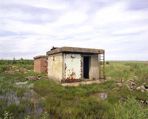
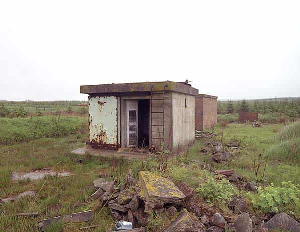
Few R7 Mk III bunkers are accessible but that at Buchan can still be found in a marshy area on the south side of the A90, the Type 79 and sub-station are clearly visible from the road and are both are both still in good condition although stripped of any original fittings. The R7 bunker is 50 yards to the south.
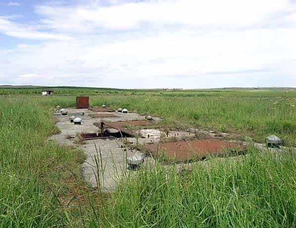
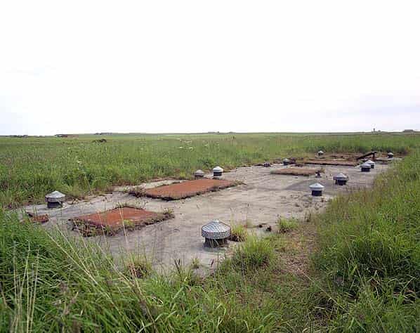
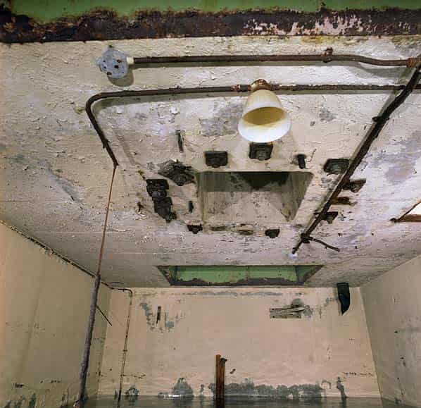
The bunker is approximately fifty feet long by fifteen feet wide. The top of it is flush with the ground. There are six rectangular apertures and one circular aperture in the roof, the largest of these was for the pedestal for the aerial array.
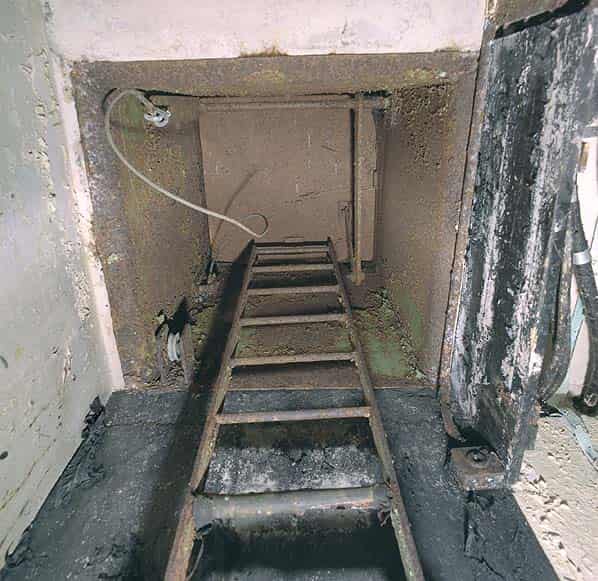
The two smallest apertures were for personnel access and each still has a ladder fixed to the wall. The remaining hatches were for the installation and removal of equipment. All the original steel hatches are still in place.
One of the personnel hatches is damaged and is permanently open; the other is closed but can easily be opened. A number of ventilators can be seen along the sides of the bunker.
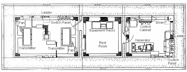
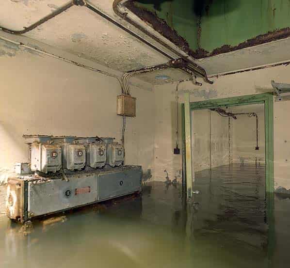
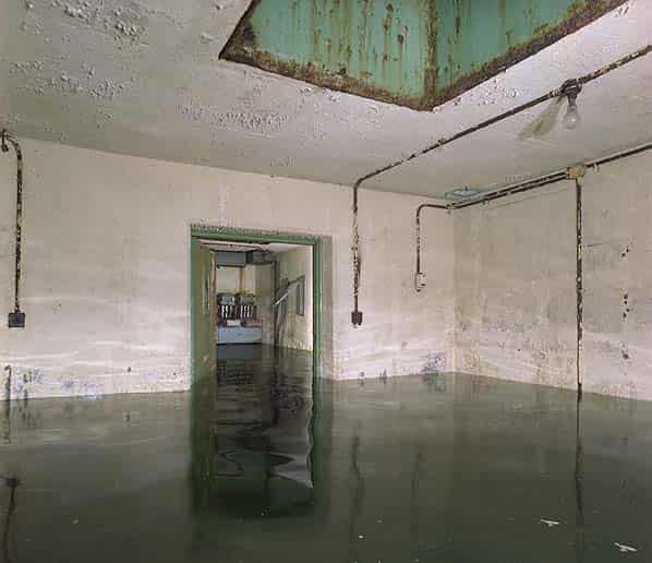
The R7 is divided into three major rooms with a closet for a chemical toilet, adjacent to one of the personnel hatches. The bunker is currently flooded to a depth of four feet; it is unclear if this is water ingress through the walls or rainwater entering the structure through the damaged permanently open hatch. The water is clear.
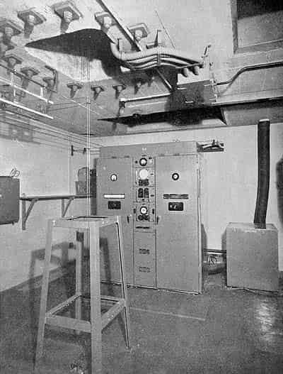
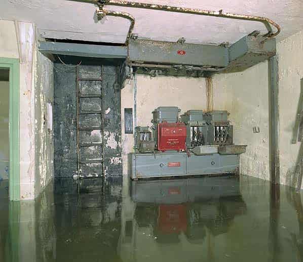
The northernmost room (15' 2" X 12' 6") was the DC plant room with a Ward-Leonard generator set standing on a plinth in one corner with the main DC control cabinet against the opposite wall and a three phase switch panel adjacent to the personnel ladder. The control cabinet and generator have gone although the low concrete plinth for the generator can still be found below the water level. The main three phase switchboard is still in place with the cable entry point and bus bar chamber above it.
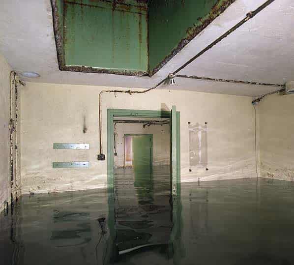
The middle room (12' 5" X 12' 6") was a rest room with three equipment racks against one wall, this is now completely empty.
The southernmost room (20' X 12' 6") was the transmitter room with two T3705 transmitters, one against each wall. All evidence of these has been removed although a single phase switch panel is still in place adjacent to the second personnel ladder. The antenna array was mounted above the large hatch in the roof in the centre of the room.
Sources:
- Bob Jenner
- Dick Barrett’s Radar Pages web site
- Signals Museum - RAF Henlow