Cold War Early Warning System
**WARNING THE PUBLIC **
From the early sixties until the early nineties at precisely 9 o’clock, the frequency of the tones used to supply the standard GPO time service TIM’s 3 ‘pips’- (‘at the third stroke’) - changed from its normal 900hz to 2500hz.
This relatively small and normally unnoticed change in the tones was part of the engineering test and monitoring process of Britain’s ‘semi secret’ telephone line based Nuclear Early Warning System.
Manual siren control
The system was not military however and its sole purpose was to warn the general populace (you and me) of impending doom! The government publication UKMWO stated “As far as the system described in these pages is concerned, experts have calculated that its contribution could amount to the saving of as many as six to ten million lives - simply by warning enough people in time!”
Whilst the system and its workings are no longer ‘secret’- (the entire system was dismantled in 1992 at the ‘end’ of the Cold War) - I do not intend to cover any political aspect but merely try to explain its workings and hence its part in our telecommunications heritage .
EARLY DAYS
The System consisted of two distinct parts, that which communicated the attack warning from RAF Strike Command to the control points (Police Stations) and that which passed the warning to the thousands of warning points across the country.
Following World War 2, the early basic system was known as SYSTEM E. It used DC signaling along private wires from control points (normally Police Stations) to the terminal Points (Sirens).
Each control point housed a Home Office supplied device the ‘Autowailer’ this was a motor driven device used to supply the timing of the 3 main signals ‘Air Raid’ ‘Raiders passed - all clear’ and ‘stop’ The GPO lines were solely used to communicate these signals to the Siren equipment.
In its normal state the A and B wires are connected to earth at the control point, at the terminal end the A wire is connected to earth and the B wire to negative 24 volts. The line relay ‘C’ on the B wire remains operated and contact C1 holds signaling relay ‘B’ in an un-operated state. Relay ‘A’ at the control point is also operated and this is used to detect any line faults or power failure of the equipment at the terminal end.
In its operated state the earth on the A and B wires at the control point are replaced with positive 24 volts and negative 24 volts respectively, this releases the ‘A’ and ‘C’ relays operates the ‘B’ signaling relay at the terminal end a contact of which is then used to switch the 3 phase mains supply to the siren. Wherever possible the equipment at the terminal end was located inside a building, normally with the siren on the roof , however in some locations a ‘street cabinet’ was used , painted green similar to GPO cabinets but looking more like ‘power’ cabinets they were 4 ½ feet high by 5 feet wide and 1 foot deep.
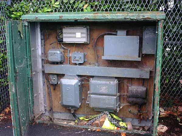
The photo shows a siren control cabinet still existing at the side of the road in South London
Within the cabinet can be seen various items, top left is the siren control panel, top right is the GPO equipment and at the bottom of the cabinet is the main power equipment and switchgear a mains powered heater was also installed. Above the siren controls can be seen a retro fitted ‘WB1400 receiver’ (a WB600 would have been mounted here until the early eighties) as this cabinet remained in use right up until 1992! (more details later).
ALL CHANGE
In the early sixties SYSTEM E was phased out and replaced with a carrier based system (carrier systems use signals not normally audible to the human ear ‘superimposed’ over the top of normal speech signals so as not to interfere with normal conversation or signaling). The early carrier systems used on ‘line’ links were known as ‘WB’ or ‘Wire Broadcast’ systems.
The System for alerting the ‘Carrier Control Points’ (the same Police Stations used by SYSTEM E) of which there were 250 spread across the country, was known by the code word ‘HANDEL’ and was cleverly designed to be sent ‘over the top’ of the existing network around the country that was used to distribute the ‘TIM’ time signal , the reason for this was two fold, one: the network already existed and would therefore save time and money and two: it was a monitored network and would therefore need no separate fault monitoring or reporting should anything go wrong.
The System was then effectively split into two the latter part of the system connecting the carrier control points to the some 18,000 warning points over ‘normal’ subscribers lines using the same philosophy of fault reporting as above - i.e. the customer would report any faults on their line, therefore negating the need for any monitoring system (unless they worked for the GPO the unsuspecting subscriber had no inkling their line was connected to such a system).
The Carrier Control Points were also connected to some 4000 ‘warning recipients’ (Civil Defence HQ’s, Hospitals and the public utilities etc.) and nearly 900 ROC (Royal Observer Corps) underground posts all of which had ‘carrier receivers’ in order to receive the broadcast warning.
HANDEL
The carrier system was sub divided into two separate but mutual systems, WB600 was used to control the Air Raid sirens and WB400 was the means by which speech and warning signals (tones) were sent to the various carrier receivers at warning points. The system used a 72Khz carrier, permanently sent down the line, this was then modulated with an AM (amplitude modulated) speech and signal tones, for reception and demodulation at the carrier receiver.
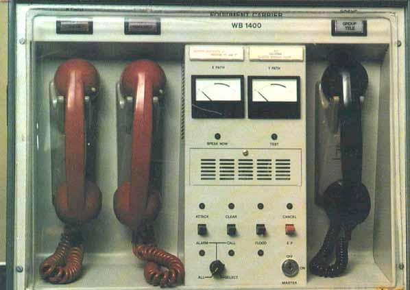
Receiver Carrier WB400 A
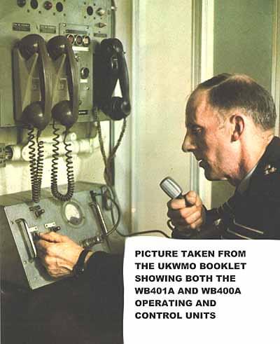
The same carrier could also be modulated with two tones (G and S) to control the switching of the sirens. The most familiar part of the system, at the carrier control point (Police Station) was the unit with 3 handsets known as the ‘Operating unit WB401A’ the two grey ‘700’ type handsets were connected to the duplicated link to the ‘TIM’ distribution system, the link was duplicated for back up reasons, and were known as the ‘X’ and ‘Y’ paths. The black Bakelite handset was connected to the nearest ROC group headquarters for onward distribution of ‘fallout warnings’ to warning points. Picking up either of the ‘700’ type handsets in a ‘non war’ situation would have resulted in the normal ‘TIM’ time signal being heard
An attack warning from RAF Strike Command would be preceded by two tones (P -2400hz and Q - 2600hz ) which signaled the WB401A to receive a message by sounding an alarm on the unit. The ‘war’ officer at the Police station would then lift one of the ‘X’ and ‘Y’ path handsets (either one would do) to receive a spoken attack warning, the system had no facility to ‘talk back’ to RAF Strike Command .
Mounted below the WB 401A was an ‘Operating Unit 400A’- normally on a table - this was the method by which the officer passed on the warning of attack/fallout to the warning point carrier receivers, there was no direct link between RAF Strike command and the ‘public’ side of the system, all messages being relayed via the Police Control Points.
The ROC posts however had direct links to their respective Group controls on dedicated Emergency Circuit Private wires but this was an entirely different network. The War Officer upon receiving the message from RAF Strike Command would operate one of three switches on the WB400A ‘Warning’,‘Speak’ and ‘Call’, Warning and Call sent a series of pulsed tones to the warning points which were received on the ‘Carrier Receiver 400 A’ to alert the warning officers, then operating the Speak key allowed the spoken warning to be re broadcast to the now alerted Warning Officers. Warning Officers would then pass on the respective warnings using hand sirens and maroons (sometimes even whistles and rattles) to the general public.
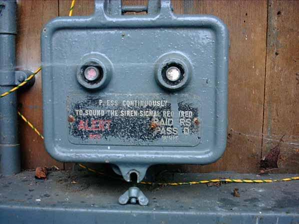
Between the handsets on the WB401A was a control unit used for setting off the Power Sirens. The unit ‘Control WB600A’ generated the two tones used to modulate the carrier ( S - 1500 Hz and G - 2160 Hz) and switch the siren controlling equipment at remote locations. To initialize the Siren circuit tone ‘G’ was sent for 10 seconds pulsed 0.4s on and 0.4s off . The ‘attack warning’ was tone ‘S’ for 4’s on and 4’s off and an ‘all clear’ was signaled by 60 seconds of ‘S’ continuous. In the photograph the button nearest the two grey 700 handsets, is ‘all clear’ the centre button is ‘stop’ and nearest the Bakelite handset is ‘attack warning’. Near the centre handset can be seen a lock switch, the key to which was held in a ‘break glass in emergency’ container.
WB600A Receiver
In the apparatus room of the Police Station the tones were generated by oscillators in a ‘Unit signaling WB600A’. This unit had a duplicate ‘Unit Control 600A’ as a backup for setting off the sirens. Also in this room would have been a ‘Unit equipment carrier WB404A’ which generated the tones and controlled the speech link to the WB400 carrier receivers at warning points. Both the above items were mounted in heavy grey steel cabinets 6 feet high by 2 feet wide. The 72KHz carrier was also generated here. At the remote siren location was a ‘Receiver Carrier WB600A’ picture of which is shown above.
The line from the Police Station was again connected (via the local exchange) to the remote siren site using an unsuspecting ‘normal’ subscribers line into a standard GPO street cabinet nearest the siren, a filter WB600 then split the line, between the customers line to their premises and the line feeding the siren control unit.
Within the WB600 receiver, the 72Khz carrier and associated tones were amplified and filtered by electronic circuitry, the filtered ‘G’ pulsed tone was then detected by a cleverly designed ‘Pendulum Relay’ the pendulum action prevented the system being inadvertently set off by speech signals on the line. Approx. 6 seconds of pulsed ‘G’ allowed the pendulum relay to swing enough to make contact, this operated the ‘S’ tone circuit. A relay in the ‘S’ tone circuit then subsequently operated the siren mains supply contacts. Mounted adjacent to the WB600 receiver was also (as per SYSTEM E) a Home Office supplied ‘Autowailer’ for manual operation of the siren .The tones generated by the WB600 system could also be heard on the WB400 receivers at warning points. Before the lines from the Police Station reached the remote sites, they of course passed through the local Telephone Exchange serving the Station .The CCE (Carrier Control Exchange) equipment, consisting of Filters and Combiners for the ‘TIM’ speaking clock feeds, amplifiers, fault monitoring equipment and ongoing distribution units were housed in a large grey or light straw cabinet. The bottom half of the cabinet had a separate section containing batteries for back up use. The cabinet was constructed of heavy steel plate with an airtight seal around a bolted down cover, all cables fed into the cabinet in a large cast iron pipe - strangely however once the cabling reached the cable racking atop the Strowger (later TXE 4) equipment the unprotected cables then wended their way across the racking to the MDF, power feeds and the ‘TIM’ network! - many engineers never could see the irony of this arrangement.
WARNING POINTS
At each of the remote sites ( Warning Points, Warning Recipients or ROC Post/Control) the line terminated onto a filter and then onto the ‘Receiver Carrier WB400’ This grey metal cased unit was the part of the system visible to the public.
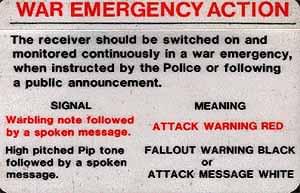
Receiver Carrier WB1400
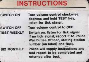
It was also of robust construction, with a cork seal and plastic membranes protecting the speaker, the interior contained a desiccant. (Although how this would have stood up to a nuclear blast was thankfully never put to the test!!) The unit had a drawer (similar to 200/300 type telephones) that contained an instruction card to be used in time of war! The reverse of the card gave routine testing details . When turned on but not receiving any signals/messages the unit gave a regular pulsed ‘tick’ known as the ‘confidence tick’ basically to let the recipient know it was on and working.
LATTER DAYS
In the early Eighties the entire system of WB600 and WB400 was replaced and updated with a combined system the ‘WB1400’. The earlier WB600/400 equipment had never been designed to be protected against an effect of a nuclear explosion called the EMP (Electro Magnetic Pulse). This pulse could wreck all electronic equipment within a large radius by destroying all semiconductors (transistors) within.
Equipment could be protected from harm by a ‘Faraday Screen’ (basically an earthed metal case). The combined WB 1400’s electronics were contained in large sealed metal cases (shown in the photographs). All the equipment mentioned earlier from the Police Station, both the WB401A/400A and all the cabinet mounted apparatus in the equipment room were replaced with one single unit the ‘Equipment carrier WB1400"’
At the warning points the WB400 Carrier Receiver was replaced with a separate metal cased receiver and loudspeaker unit ‘Receiver Speech WB1400 and Loudspeaker unit WB1400’.
At remote siren sites the WB600 unit was replaced with an identical looking ‘Receiver Signaling WB1400’ but no loudspeaker.
WB1400
The later WB1400 system used the same 72 kHz carrier and signaling as the earlier WB400/600 so a relatively seamless changeover could occur.
The main differences were the aforementioned EMP protection, line powering to eliminate the need for constantly changing batteries and extra signaling, (including “flood” warnings).
The WB400 receiver was powered by a battery, which often went flat, the units having been left on in error, (the units should only be turned on for use or testing ).
The WB1400 receiver however was permanently ‘on’ in standby mode, the internal battery being ‘trickle charged’ by a line current. An extra tone signal (pulses of 620 Hz) sent from the WB1400 control point would ‘alert’ and turn on the receiver ready to receive further signals or speech.
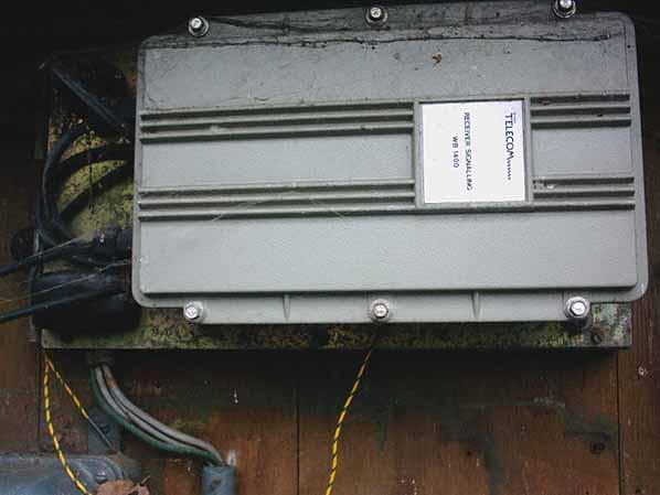
Receiver Signalling WB1400 mounted sideways in cabinet
ROC POSTS
Lines installed into ROC (Royal Observer Corps) posts also had means by which the observers could communicate directly to their Group control and other posts. The equipment which shared the same pair of wires as the WB equipment was known as ‘Teletalk’. This was an ‘intercom’ system permanently on receive that required the pushing of a button on the unit to speak.
Early WB400/600 era units were known as ‘Unit Intercom AD 3460’ (AD stood for Air Defence) and used two batteries 67.5v for signaling and 6v for speech. The later WB1400 era version ‘Loud speaking Telephone AD 8010’ was line powered. Both units required the use of a filter between itself and the WB carrier receiver.
Equipment Carrier WB1400. This replaced Equipment Carrier 401A and 400A
Many of the lines to ROC posts were only live when required and during testing. Known as EC or Emergency Circuits the lines were switched or turned on by either engineers or traffic staff. Each exchange that served a ‘post’ was equipped with a ‘Unit Observer Post Switching’, a written form THQ 2775 was submitted to the GM (general manager) of the respective telephone area by the ROC in order to request the lines to be turned on!
This, believe it or not, was a ‘cost exercise’ the ROC not being charged for the lines when not in use !
FLOOD
In areas that so required it the system was also equipped to warn of flood. The originally separate WB601 Flood warning system was incorporated into the WB1400 system, although in some areas (especially London and the Thames) ‘WB1401’ carrier receivers were used where the flood siren was unconnected to the Air Raid system (confusingly ‘1401’ was also used to describe a more robust speaker unit ‘loudspeaker unit WB1401’ used in damp areas in place of the normal ‘loudspeaker unit WB1400’).
The flood signaling used the same network and carrier, with differences to the signals and timing (of the siren) In flood alerts the ‘G’ signal was sent for a pulsed 115mS on and 115mS off. This part of the system was controlled from the Police Station ‘Carrier Control Point’.