Air Commodore Keith Park, Air Marshall Dowding’s Senior Air Staff Officer (SASO) was delegated the job of siting the RAF’s radar stations on the Isle of Man. He was later Air Vice-Marshall and AOC at 11 Group, responsible for Battle of Britain from the underground headquarters at RAF Uxbridge.
Discarding scientific advice from Bawdsey to site a Chain Home station on the summit of Snaefell, Park preferred the option of two Chain Home stations, one at the north end of the island and the other to the south.
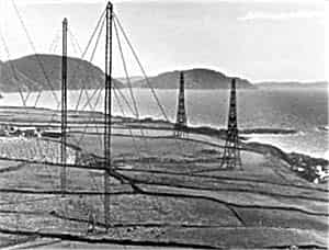
The sites selected early in 1940 were Bride at the north (SC463031) and Scarlett to the south. Both sites were designated Advance Chain Home (ACH) installations being brought on line with temporary shorter timber masts to support the transmitter arrays, pending the availability of standard ‘west coast’ 325 foot guyed steel masts. Both stations were in use by September 1940.
Subsequently, Bride was found to be surplus to requirements being covered from Scotland and Ireland to the north and by 1942 it had been closed and stripped of equipment. Scarlett did not last much longer.
The Island’s airport at Ronaldsway had been requisitioned by the Air Ministry in 1940, but in the first quarter of 1941 they agreed to the transfer of the grass airfield to the Admiralty for development as a fleet air arm training unit. It was renamed HMS Urley. As Scarlett’s 325' aerial masts were well inside the mandatory 6000 yard construction limit, the station was closed shortly after the completion of a new station at Dalby in 1942 with both stations running simultaneously for a time to ensure unbroken cover. With the closure of Scarlett, Dalby remained the only CH station on the island for the remainder of the war.
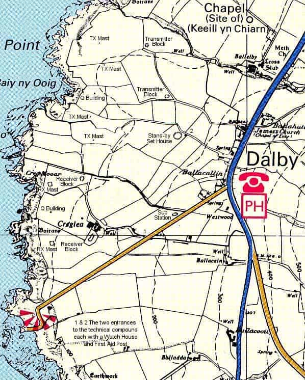
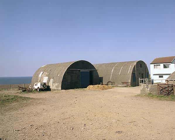
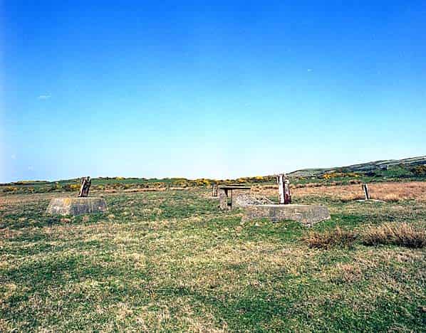
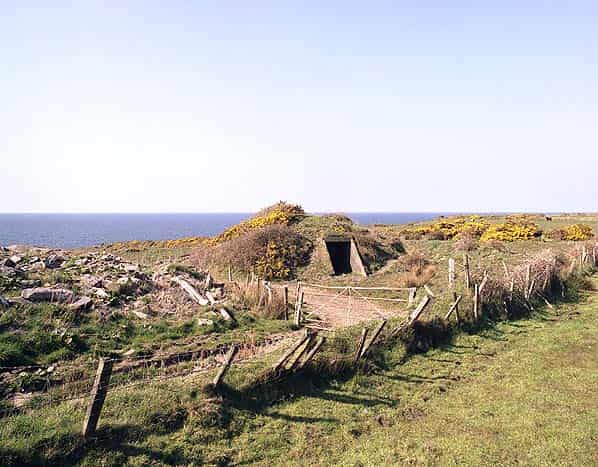
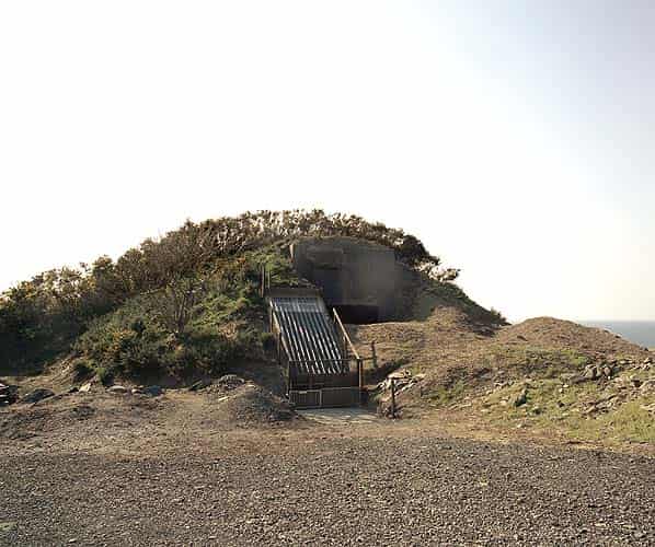
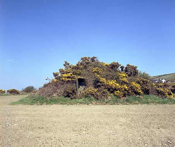
At Dalby the radar station is now spread over two farms, Creglea and Ballahutchin Mooar. Each farm has two C type operations blocks. The receiver blocks are on Craglea Farm at SC21407799 (close to the farm buildings) and SC21387823, both are now used as cattle sheds. There is an entrance at both ends of the block. Close to the second block are the bases of one of the receiver aerial towers at SC21257820. This consists of four concrete bases with a metal framework supporting a few feet of the timber tower. In the middle of the site is a small brick building. The underground cables came up into this building.
There are several camp buildings close to the farm and a third bunker alongside the road leading to the farm at SC21707806. This bunker is much smaller and was originally divided into three rooms each with a separate entrance on three sides; this originally housed the substation.
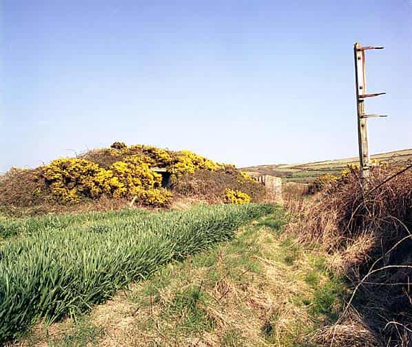
The transmitter blocks are on Ballahutchin Farm at SC21757842 & SC21707850, unusually two of the aerial feeder poles are still standing close to one of the blocks. The stand-by set house, a particularly large bunker with one entrance is at SC21697853 close to one of the two original entrances to the technical compound.