In the summer of 1989 Blue Circle Industries PLC invited the Sussex Industrial Archaeology Society to survey the kiln situated at their landfill site at Beddingham in East Sussex. It was their intention to demolish the kiln as there was a danger of explosive gases accumulating in the underground voids. The only access at that time was from the top by descending some 45 metres to levels 1 and 2. An accurate survey of the top level (5) and a rough survey of the lower levels was undertaken in December 1989 and January 1990, the work to the lower levels being carried out under considerable difficulties due to bad air which limited the time available on site; it was anticipated that no further investigation would be possible. In December 1990, the outer end of a tunnel at level 2 was exposed and easier access obtained. Furthermore a level 0 was discovered below level 1 together with another tunnel; a new survey of all lower levels was then completed. At this time members of Subterranea Britannica joined the SIAS team to make a photographic survey.
Portland cement was patented by Joseph Aspdin in 1824 being manufactured from a mixture of chalk and clay fired at a temperature of 1400C. The use of Portland cement increased dramatically during the last part of the nineteenth century. As it was mostly made in intermittent kilns by the turn of the century an acute shortage had arisen. Continuous rotary kilns had been invented by that time, the first being patented in 1877. After various unsuccessful attempts had been made in this country they were being developed abroad making the large scale production of cement more economic. Rotary kilns were expensive both to construct and to maintain and the system of mixing the chalk and clay as a wet slurry meant that there was considerable wastage of fuel in the evaporation of the moisture before calcination could take place. In spite of this, there were 68 rotary kilns in production in England and Wales in 1914 out of a total of 617 kilns and by 1927 the first 300ft. rotary kiln had been built.
Various individuals in the 1920’s proposed methods of making cement by cheaper methods. Vertical shaft kilns with few moving parts were suggested and Sir Percy Girouard designed one that was patented in 1926.
Sir Percy’s design envisaged a vertical shaft constructed near the face of a quarry with the shaft narrowing towards the bottom where pulverised fuel would be supplied through nozzles. The powdered material for making the cement would be showered down from the top of the kiln and meet the upward flow of hot gases and the particles would be thoroughly burnt before passing into the lower cooling chamber where they would be removed and ground. This design of kiln used the ‘flotation’ process of firing with waste heat being recycled and used in the process. It is not known whether a kiln was built to this specification.
Dr. Geoffrey Martin, an eminent chemist and the author of many standard reference books on industrial chemistry, improved on the design of Girouard’s Flotation Kiln and patented his own design in 1927. This endeavoured to balance the up flowing hot gases with the descending raw materials and employed a cyclonic action with the upper part of the kiln widened toward the top. Pulverised dry raw material was discharged into the kiln at the downward part of the gas movement. Exit gases were drawn off on the same side as the entry of the raw material. The cross sectional areas of the respective parts of the kiln and the velocities of the gases were carefully calculated to achieve maximum calcination of the raw materials. The fuel in the form of powdered coal was injected into the sides of the kiln at the bottom with a cooling zone beneath this. The advantage of the flotation kiln as anticipated by Dr. Martin, was that the materials being in suspension were capable of being thoroughly intermixed without all the disadvantages of wet mixing. As compared with other shaft kilns the pre-heating zone and calcining zones were filled not with large blocks of material that impede the passage of hot gases, but with small particles in suspension. This would allow large volumes of gases to pass at any given time and hence enabled a large output of clinker to be produced.
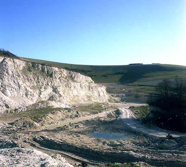
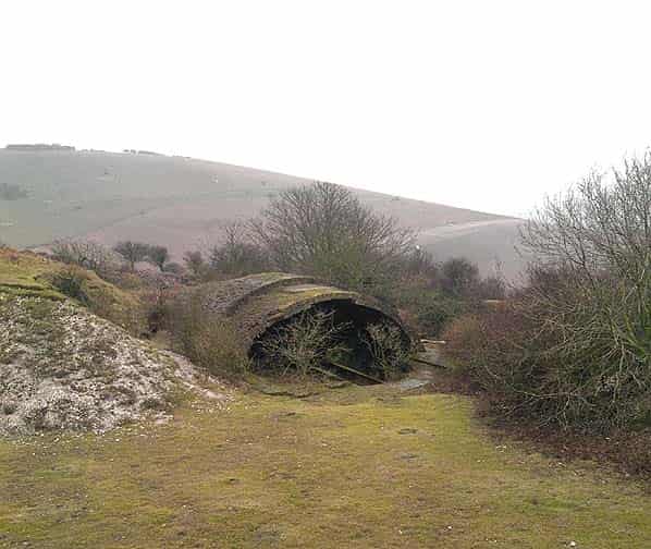
In 1928 Dr. Martin built a large-scale experimental underground flotation kiln within a quarry face at Asheham in the parish of Beddingham near Lewes. All the tunnels and other excavations were carried out by hand and the equipment was manhandled into position.
This kiln was substantially similar to that shown in Dr. Martin’s Patent. The main differences being that the plan shape which in the Patent was rectangular is now oval and the upper part of the kiln previously parallel sided now enlarges towards the top and the raw material is now discharged down a pipe rather than through the side of the kiln. Experiments were carried out for three months, concluding in December 1929. Reg Duplock, who worked in the kiln, described how pulverised coal was conveyed by means of skips for 150 yards along a tunnel and into the burning chamber. Dr. Martin, writing in 1932, described the results as being “most promising and it is hoped, after making certain alterations, to remedy technical defects which revealed themselves in the trial, to proceed to manufacture clinker by this new process in the near future”. It is not known if any further trials were carried out.
It is presumed that the kiln was abandoned for the experimental manufacture of cement after December 1929 but it seems probable that subsequently attempts were made to burn lime on the site.
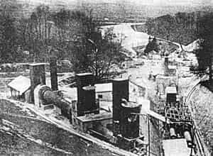
On the other side of the road, the Rodmell Works was established by Cement Industries Ltd. as a cement works with a rotary kiln; building starting in 1932. An important figure A.Y. Gowan, an American who became interested in reorganising the British cement industry at this time had visited Asheham. He set up the Alpha Cement Co. Ltd. in 1933 and bought out Cement Industries Ltd. By this time the success of rotary kilns was established and any desire on the part of Alpha to continue research into the shaft kiln would have been futile.
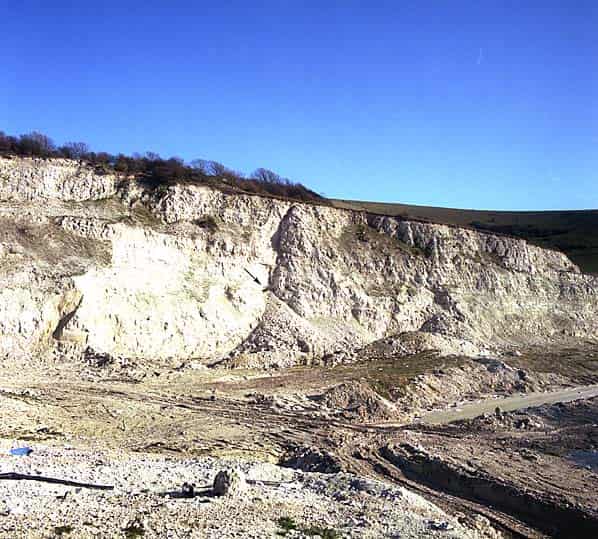
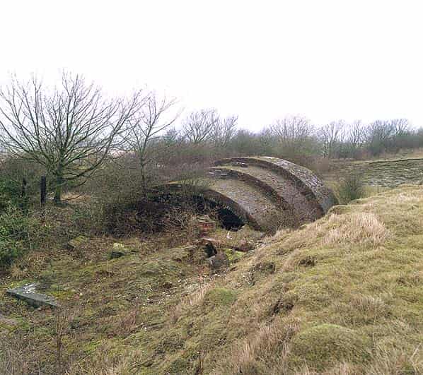
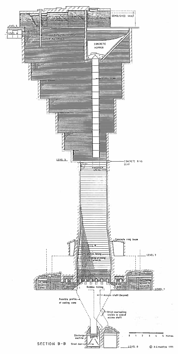
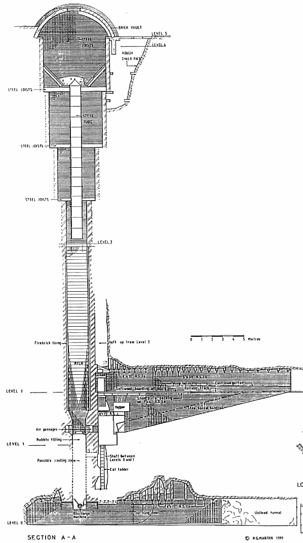
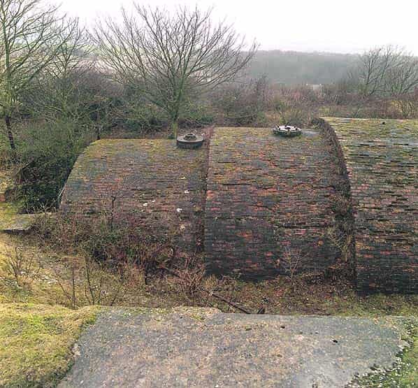
The kiln is built on a spur of the Downs which extended westward into the Ouse valley and has now been substantially excavated as Pit No.3. It comprises a shaft, oval in plan 15.3 m X 6.0m at the top level (5), reducing in size in a series of steps to a rectangle with semi-circular ends, 3.9 m X 1.9 m at level 3. The walls of this upper part of the kiln are one-and-a-half bricks thick and are supported on reinforced concrete ring beams spanning between concrete counterfort walls built between the kiln and the surrounding chalk. The top of the kiln is covered by four three-ring brick barrel vaults of varying spans, although the vault at the north end has now collapsed. In the crown of each of the barrel vaults there are circular steel plates with apertures in the middle.
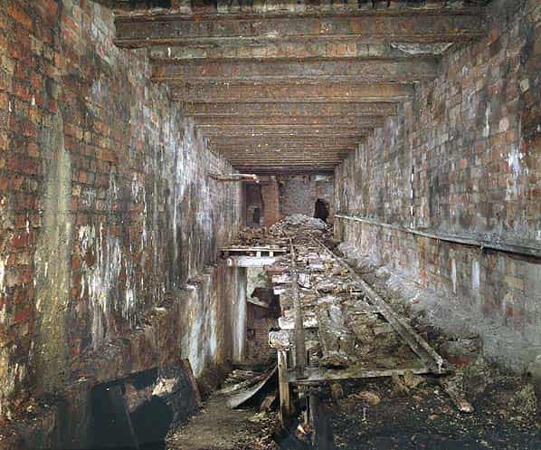
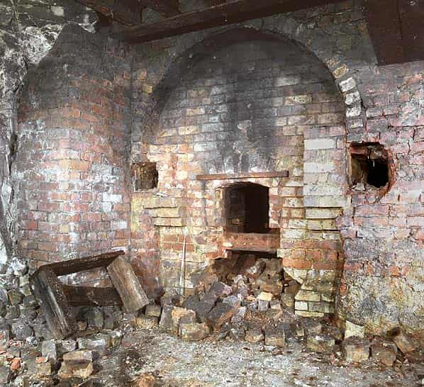
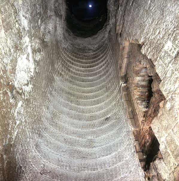
For the next 15.7 m below level 3 the kiln lengthens from 3.9 m to 5.1 m with oversailing courses. The kiln walls are lined with firebricks, laid on end, with special culvert bricks to the curved ends. Below this both long sides are shouldered to reduce the width of the kiln to 1.1 m and the inside of the kiln is lined with brick.
This shouldered portion shows considerable signs of striation and erosion. There is no access to the interior of the kiln below level 1 as the bottom is filled with rubble. At the south end of the kiln, immediately below level 5, there are three chambers with concrete walls, floors and tops and with access to the centre one from the side of the kiln. There appears to be no purpose for these chambers and they may relate to the original construction.
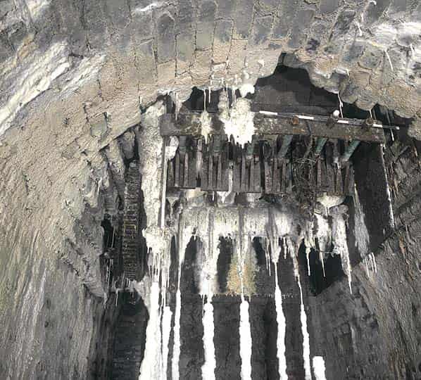
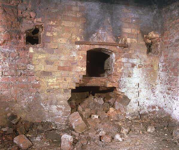
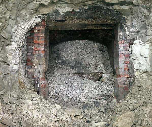
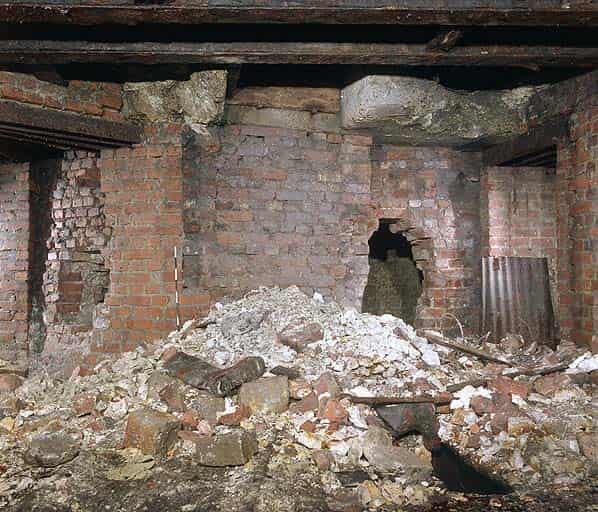
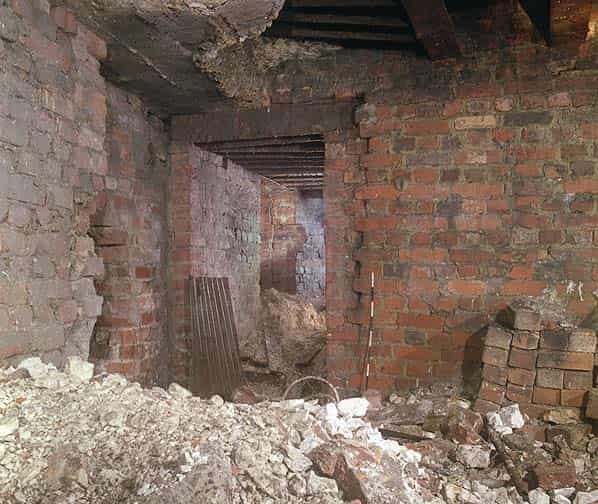
At level 1 there are fire boxes and both ends of the kiln with ‘stoking holes’ in two parts and a cast iron z-section beam across the centre of the openings, below which was probably some form of mechanical stoker, as the brickwork was neatly cut around some item of machinery, now missing. There are horizontal ducts in the thickness of the walls running along both sides of the kiln and fire boxes, with vaults over and access holes into the kiln (six each side) and into both fire boxes (two each side). There are also openings cut from the horizontal ducts into the service passages and at both ends.
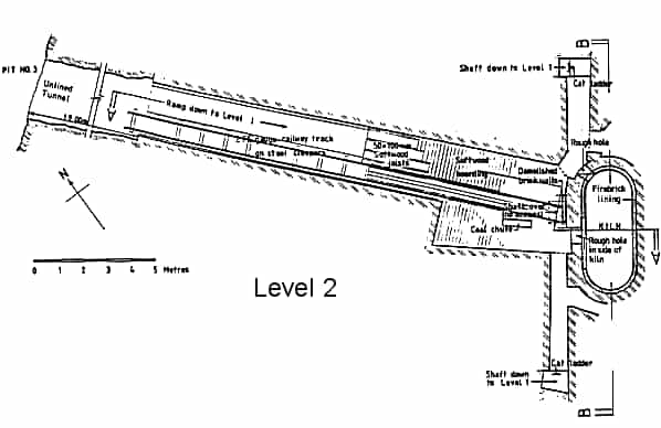
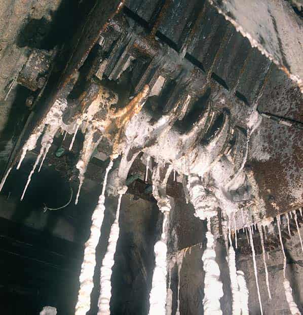
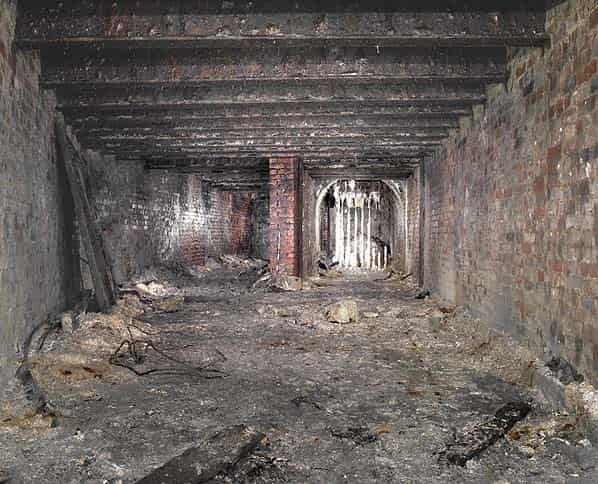
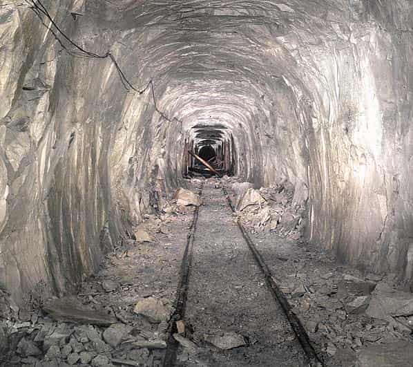
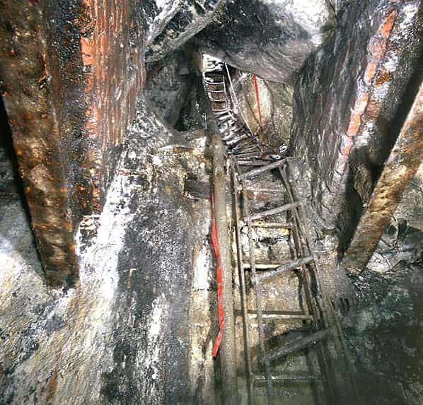
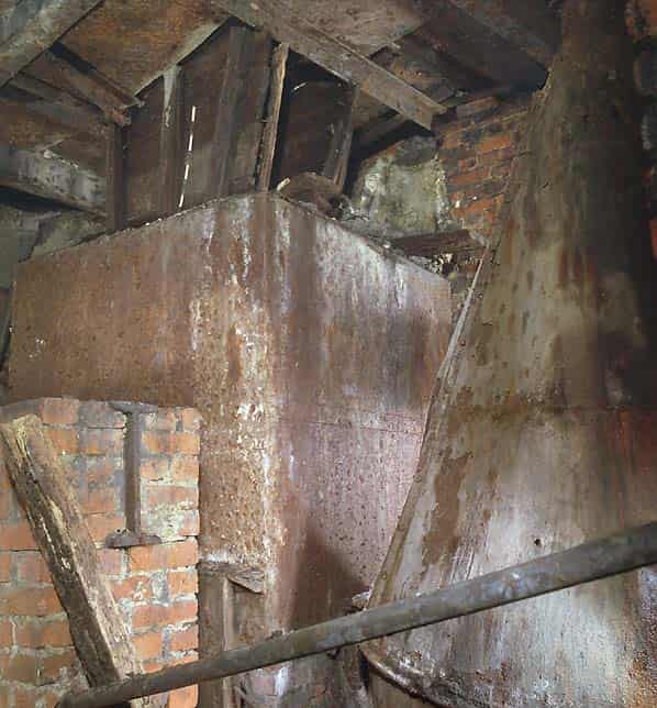
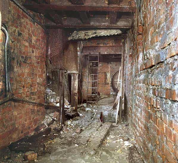
Outside the kiln there are service tunnels on levels 1 and 2. These areas are lined with brick and the chalk soffit is supported by steel joists with brick pinning walls over. The floor of level 2 consists of sheet steel supported by steel joists and covered by softwood flooring on bearers. From level 2 an unlined tunnel cut in the solid chalk runs westwards along which is laid a 2 foot gauge railway line on steel sleepers. There is an aperture in the floor beside the railway track connected to a timber chute discharging into a steel hopper with two outlets. A ramp leads down from level 2 to 1.2 m above level 1 with a ladder below this and there are also two vertical shafts with ladders between the two levels; a heap of coke lies in the southwest corner of level 2.
At level 1 there are various machine bases with holding down bolts. Located adjacent to the fuel hopper but unfixed is a steel cylinder with a conical top. There is a rectangular outlet at the base presumably previously connected to an air duct.
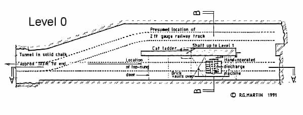
Level 0 is accessed by a part-vertical part-sloping shaft and ladder. This comprises an area that tapers at one end with brick walls and a brick dividing wall. The support to the soffit is as the upper levels. At one side of the dividing wall there is a discharging machine that is situated immediately under the centre of the kiln. The lower part of the kiln is blocked with rubble but it is presumed that there is an even taper from level 1 down to 2.0 m above level 0.
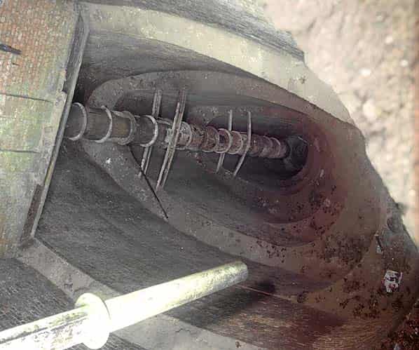
The machine under the kiln consists of a shaft with a series of cast iron hook-shaped claws at the end, operated via a system of gears by a hand-operated crank. Burnt clinker would be discharged through the bottom of this machine into railway trucks which ran on another 2 foot gauge railway.
One railway line ran straight from the bottom of the kiln down an unlined tunnel of which there is still about 100 m extant. The line stops at 40 m from the far end at a timber sleeper that has apparently been used as a buffer stop. At the end one of the tipper trucks was buried beneath the end of the blocked tunnel that has now been cleared and the truck removed. There was a branch line that ran down the north side of the dividing wall and a length of curved track is extant but not in position. There is a gate located close to the discharge machine but not in its original position. This was top hung from a steel joist and operated by a rope and tackle. There are two cut outs where the gate is closed over the railway tracks.
The upper 7.2 m of the kiln is divided laterally by a brick wall supported on two steel joists with a concrete hopper on one side, from the bottom of which there is a steel tube that extends downwards for at least 14.5 m. The top is bell mouthed and closed with a conical damper connected to a wire rope. Beneath the damper there appears to be another shutter as there is evidence of water being trapped about 2 m below hopper level. It would appear that this wall and hopper was installed after the kiln was constructed.
At upper ground level around the kiln there are various structures and machinery bases. The fuel was conveyed into the kiln by means of the tunnel at level 2. The raw materials would have had to be conveyed to the top of the kiln probably using a steam winch that hauled narrow gauge wagons up from the quarry to the top of the lime kiln. There are remains of wire ropes and bases which could be supports for the winch or similar. Due to the topography of the site it would not have been practicable for materials to be transported to the top of the kiln by any other means. The slopes would have been too steep for any vehicles available at the time and furthermore there are no signs of any roadways or tracks at the top.
For the kiln to operate in the way envisaged by Dr. Martin, the fuel would probably have been injected into the fire boxes by means of some mechanical device. This probably accounts for the shape of the lower part of the holes from the service areas to the fire boxes which are identical at both north and south ends. The interior of the fire boxes and the air passages along the side of the kiln are all affected by heat. The apertures directly from the fire boxes to the kiln are not fire-affected and it is possible the fuel feeding mechanism extended into the kiln. The openings apparently cut from the access areas into the air passages might possibly have been the means of getting the forced draught into the kiln or were cut in order to clear clinker blocking the air passages.
All the access areas are wired for electricity so this would have been available to power the fuel feed and forced draught apparatus.
After the clinker had descended to the base of the cooling zone would be removed through the discharging machine on level 0.
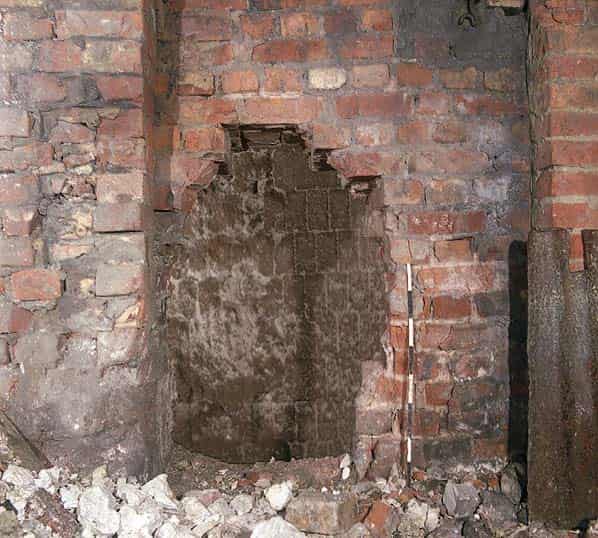
It is considered possible that there would have been some means of providing a hot bed to commence the process of firing. Although the shape of the cooling zone has not been determined there is a blocked arched aperture visible in the side below level 1 and some evidence of a level floor.
The hot gases being drawn from the top of the kiln, according to Dr. Martin would pass through a waste heat boiler, controlled by a damper, then through a fan and on to an exhaust chimney.
It is certain that alterations have been made to the kiln and these probably relate to the attempts in 1931-32 to use it as a continuous mixed feed lime kiln. The hopper at level 5 with the brick dividing wall and the steel tube are probably of this phase. There is evidence of chalk and coke present in the hopper and the conical damper would be the normal way of controlling discharge from a hopper into a kiln. The fact that it then passed down 14.5 m of tube merely indicates that only the bottom part of the kiln was actually being used. It is also possible that the horizontal part of the flue is associated with this as there is an offset at the junction with the end of the kiln and some of the brickwork there is not properly bonded in.
This kiln probably represents the only example of this type in existence and was an interesting experiment that if it had proved successful might have seen the adoptions of shaft kilns instead of rotary kilns for the production of cement. Due to its location in relation to the landfill site there is no way that the kiln can be preserved. I have however been given every opportunity and assistance from Blue Circle Industries PLC to enable a full record to be made before its ultimate destruction. When this happens further evidence may come to light as to its construction.
Sources:
- HMSO 104th Annual Report on Alkali &c. Works by the Chief Inspectors (1967)
- Sir Percy Girouard, British Patent No. 260.608; (application date 7 Aug 1925; complete acceptance 8 Nov 1926)
- Geoffrey Martin, British Patent No. 276.066 (application date 17 May 1926; complete acceptance date 17 Aug 1927)
- Geoffrey Martin, Chemical Engineering and Thermodynamics Applied to the Cement Rotary Kilns etc. (1932) 28.16-20
- Blue Circle Vol 27 No. 1 (1972) 6. Martin, Chemical Engineering 28.21
- P. Lesley Cook, Effects of Mergers (1958) 92-3
- Ibid 28. 6-20